What inspection variables should be evaluated?
Place the scan line inside the useful light band. Then check synchronisation and image proportions as speed changes.
What lighting geometry fits this inspection task?
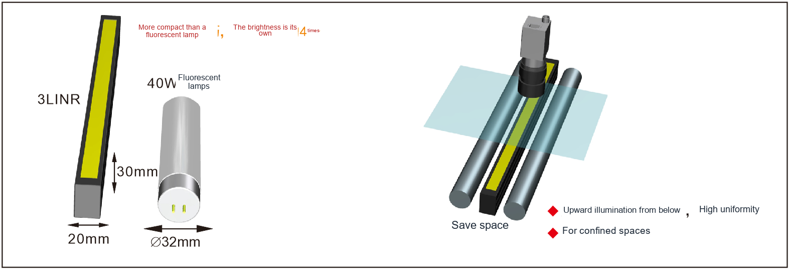
Align the illuminated line with the camera scan line and cover the complete inspection width. Compare brightness, working distance and line width together; housing length alone is not enough. Continuous motion also needs stable triggering and speed information.
Fix line rate and exposure, compare both ends with the centre, and check moving samples for smear and banding. Cooling affects sustained operation, so repeat captures after temperature stabilises. Record speed, mounting angle and controller settings to make the setup reproducible.
Related product family?
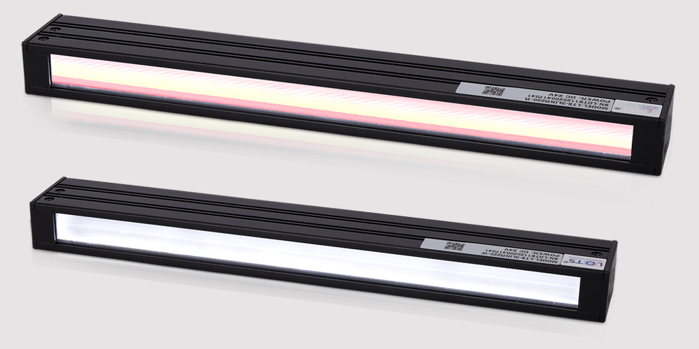
LXV-3LINR
A focused line of light for inspecting surfaces and edges.
Before choosing a configuration?
For selection, specify the field of view, smallest target feature, height variation, cycle time and installation space. Use the specific product page and drawing to verify electrical ratings, dimensions and compatibility.
Synchronising a line-scan station?
Align the illuminated line with the sensor's object-space line and the travel direction. Match line rate to motion using the appropriate timing source. Check the field at the actual lens aperture and working distance.
Capture a geometric reference while the part moves. Verify pixel aspect ratio, full-width coverage and exposure margin. Inspect the reconstructed image for seams or brightness changes caused by timing and speed variation.
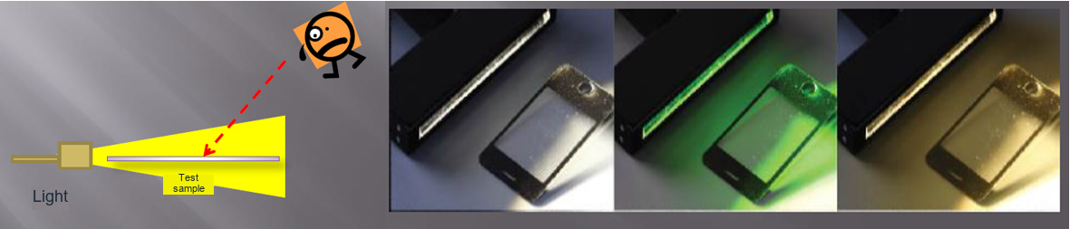
What do the optical setup and sample images show?