

Case 01
Automotive Reflective Strip Defect Inspection
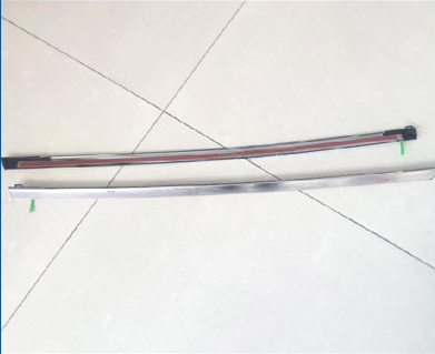
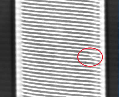
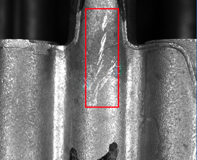
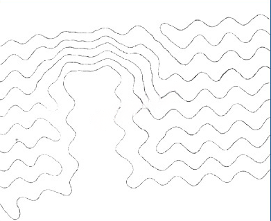
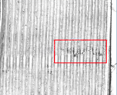
Reflective automotive strips are difficult defect targets. Grating flat shadowless illumination reveals defects through deformation in the reflected line pattern.
Each scene names the surface and the light. Send the part for that series.
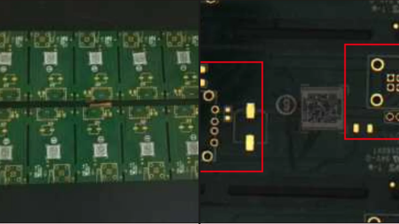
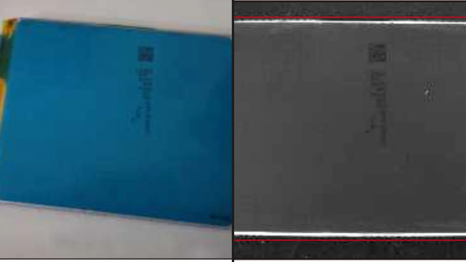
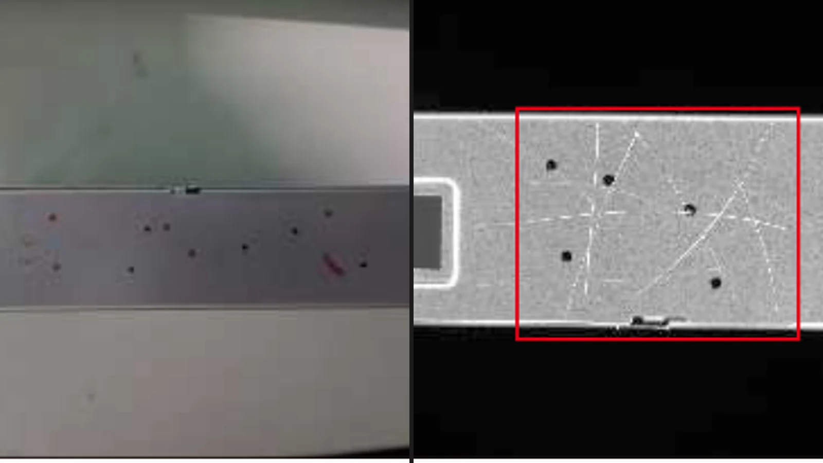
Identify the feature or defect, material, geometry, and surface response before naming a product family.
Use angle, wavelength, diffusion, strobe behavior, and optical control as the comparison variables.
Validate field of view, working distance, camera, lens, speed, and mounting limits with the actual part.
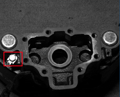
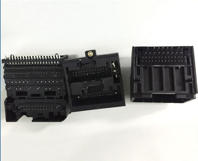
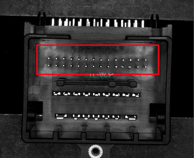
Automotive inspection includes reflective strip defect detection and connector pin alignment where glare control and pin-edge clarity are critical.
Reflective automotive strips are difficult defect targets. Grating flat shadowless illumination reveals defects through deformation in the reflected line pattern.

High-angle ring illumination from a near-vertical direction makes pin tips and outlines clearer for robotic pickup and alignment.
Compare workpiece baseline photographs against optical inspection results and jump directly to the tested LuxMV series.
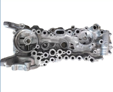
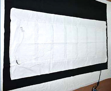
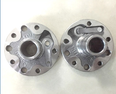
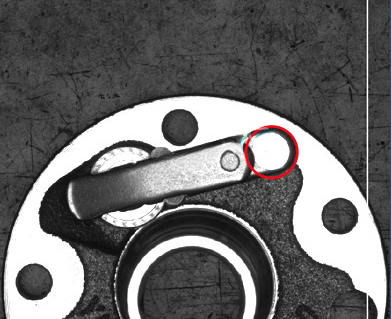
Gasket presence and orientation; Reflective trim defects; Casting surface defects; Steering-wheel heating wires.
Oblique or low-angle lighting can darken a smooth background while allowing scattered light to reach the camera. Scratch visibility depends on direction, depth and illumination angle. Separate images from several directions may be needed. Hold the part fixed and vary the light direction. Compare normal texture with actual defects rather than judging brightness alone. Check shadows, curved-surface highlights and motion blur. Repeat the test at production speed and across the permitted position variation before choosing a layout.
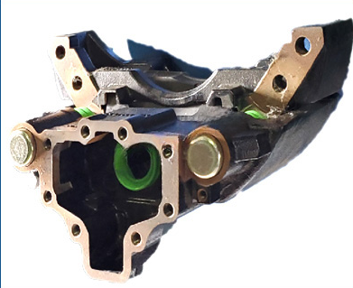
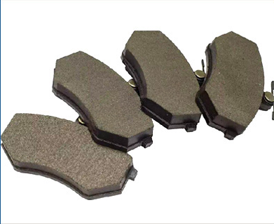
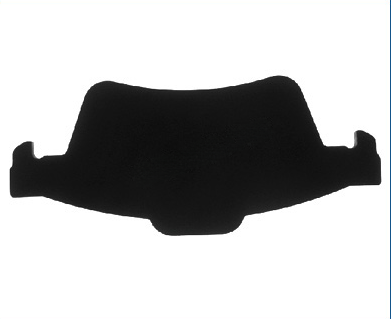
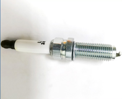
Automotive connector pins; Brake pad outlines; Spark plug threads; Assembly rivets.
Ring lighting surrounds the lens, but different illumination angles produce different images. Higher angles can illuminate surfaces facing the camera; low angles can reveal edges and relief. Hole depth, occlusion and surface reflectance matter. Confirm that the clear opening does not restrict the field of view. Compare target and background at different light heights. Inspect peripheral pins, corners and recesses as well as the centre. Keep the sample pose controlled, then test throughout the permitted tilt range.
Use it to identify the material, feature, reflection condition, and imaging task, then confirm the camera, lens, field of view, working distance, speed, and production limits with a sample test.
No. Application examples show selection patterns; final suitability depends on the actual material, finish, geometry, camera setup, and production conditions.