Ring backlight for boundary, transparent-material and liquid-level inspection
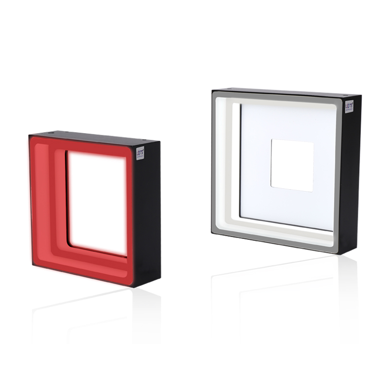
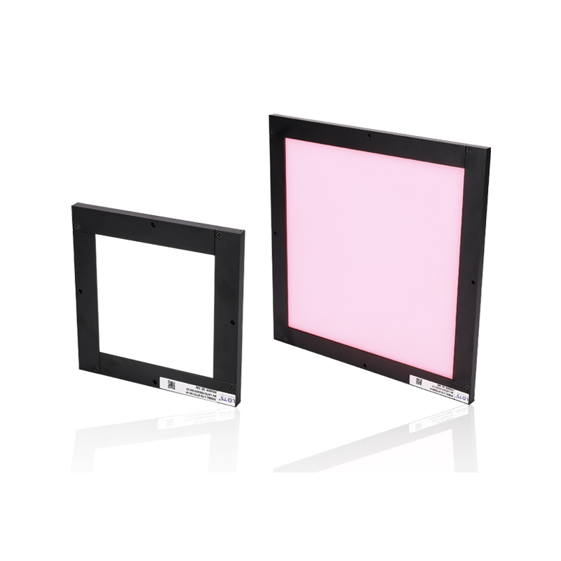
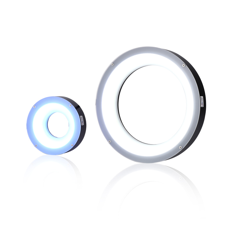
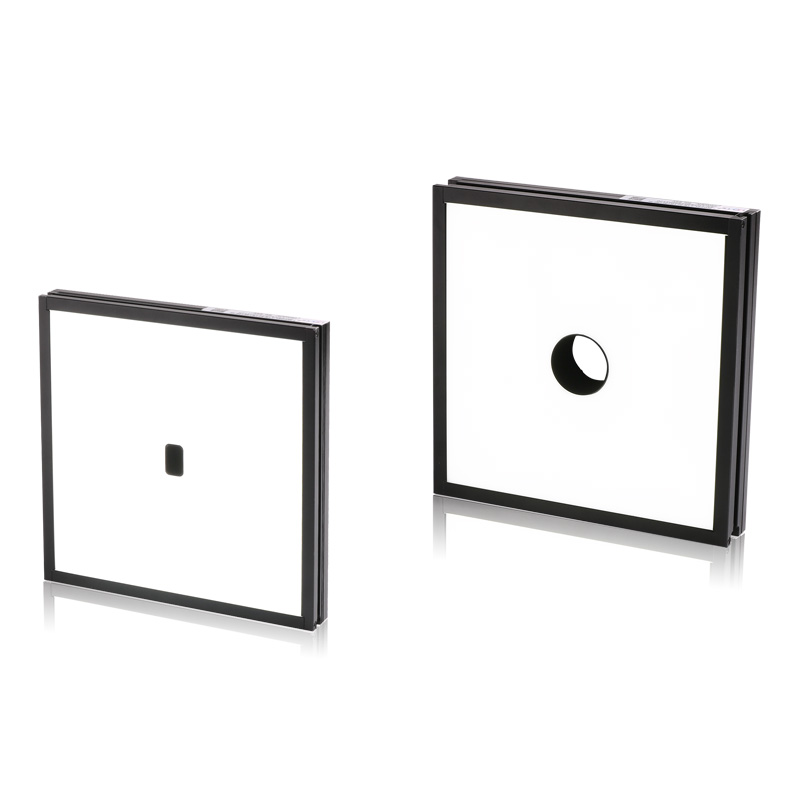
LXV-4FTB, LXV-4FTR and LXV-3FTR place high-density LEDs behind a luminous field with a centre opening. The family combines high uniformity and luminance with square or round viewing apertures, and supports configured emitting area, opening, colour, cable, installation and multi-area control.
- Standard models
- 19
- 5 × 4FTB, 5 × 4FTR and 9 × 3FTR
- Supply
- 24 V
- Every listed standard model
- Emitting fields
- 90 × 90–1000 × 700 mm
- Exact model dependent
- Centre opening
- 20 × 20–70 × 40 mm or Ø30–Ø65 mm
- Family and model dependent
- Power
- 5.9–390.0 W
- Colour and model dependent
Boundary dimension measurement
Place the part in front of the luminous field and measure its outer silhouette through the centre camera path.
Damaged-edge inspection
Use transmitted contrast to expose chips, missing material and edge discontinuities.
Transparent impurity inspection
Reveal inclusions or foreign matter inside transparent targets against the bright field.
Oral-liquid level inspection
Measure the liquid boundary while the centre opening keeps the viewing path available.
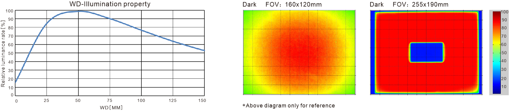
Working-distance response and field uniformity for LXV-4FTB236186-W
The measured reference separates the working-distance curve from two irradiance fields so each axis, field size and centre opening remains readable. The curve is normalised to its maximum, while the maps use a 10–100 relative scale.
Relative illuminance by working distance
The measured curve covers WD 0–150 mm. Relative illuminance rises from about 15% at WD 0 mm to 100% around WD 50 mm, then falls to about 53% at WD 150 mm.
Relative-irradiance fields
The 160 × 120 mm field shows the central intensity distribution. The 255 × 190 mm field preserves the central rectangular opening and the full 10–100 colour scale.
Configurable construction
The body can be configured for viewport, emitting length and width, multi-area control, colour or colour temperature, cable length and installation method.
Measured optical references
The entries below restate the labels and relationships visible in the three measured plots.
| Reference | Documented range | Key reading |
|---|---|---|
| WD–illuminance property | WD 0–150 mm; relative illuminance 0–100% | Maximum is normalised to 100% around WD 50 mm |
| Dark field 1 | FOV 160 × 120 mm | Central output is highest and decreases toward the perimeter |
| Dark field 2 | FOV 255 × 190 mm; relative scale 10–100 | High-output rectangular field surrounding the centre opening |
- LED arrangement
- High-density LEDs at the bottom of the light
- Output
- High uniformity and high luminance
- Configurable geometry
- Emitting area and centre opening
- Measured model
- LXV-4FTB236186-W
Select one of the 19 documented standard geometries
The three families use different opening shapes and housing depths. Keep emitting field, centre opening, boundary envelope, weight, power and common-status value on the same row.
- 1
Set the illuminated field
Cover the complete silhouette or transparent target plus positioning tolerance.
- 2
Size the viewing aperture
Use a rectangular 4FTB opening or the specified round 4FTR/3FTR opening without blocking the camera path.
- 3
Choose colour and power
Red and G/B/W loads differ; size the 24 V controller from the selected row.
- 4
Confirm the physical row
Release the exact boundary envelope, weight and common-status value with the model.
Read the product model pattern
LXV-[4FTB|4FTR|3FTR][length][width]-[D opening]-R/G/B/W/IR/UV- LXV
- Product prefix
- 4FTB / 4FTR / 3FTR
- Ring-backlight construction
- Length / width
- Emitting-area dimensions
- D opening
- Round opening diameter where used; 4FTB rows use rectangular openings
- R / G / B / W / IR / UV
- Output colour or wavelength
LXV-4FTB standard models
4FTB uses rectangular centre openings. Power is shown as red / green-blue-white.
| Model | Voltage | Power R / G-B-W | Emitting area | Centre opening | Boundary dimension | Weight | Common |
|---|---|---|---|---|---|---|---|
| LXV-4FTB9090 | 24 V | 5.9 / 7.4 W | 90 × 90 mm | 20 × 20 mm | L104 × W104 × H21 mm | 265 g | Y |
| LXV-4FTB110110 | 24 V | 6.4 / 8.0 W | 110 × 110 mm | 40 × 40 mm | L146 × W124 × H21 mm | 514 g | Y |
| LXV-4FTB140140 | 24 V | 13.8 / 17.5 W | 140 × 140 mm | 40 × 40 mm | L154 × W154 × H21 mm | 721 g | N |
| LXV-4FTB200100 | 24 V | 12.2 / 15.4 W | 200 × 100 mm | 40 × 40 mm | L214 × W114 × H21 mm | 742 g | Y |
| LXV-4FTB236186 | 24 V | 27.5 / 35.4 W | 236 × 186 mm | 70 × 40 mm | L250 × W200 × H21 mm | 1,125 g | Y |
LXV-4FTR standard models
4FTR uses round centre openings. Power is shown as red / green-blue-white.
| Model | Voltage | Power R / G-B-W | Emitting area | Centre opening | Boundary dimension | Weight | Common |
|---|---|---|---|---|---|---|---|
| LXV-4FTR120120 | 24 V | 9.6 / 12.2 W | 120 × 120 mm | Ø30 mm | L134 × W134 × H17 mm | 382 g | Y |
| LXV-4FTR141141 | 24 V | 12.2 / 15.4 W | 141 × 141 mm | Ø35 mm | L155 × W155 × H17 mm | 801 g | Y |
| LXV-4FTR150150 | 24 V | 15.9 / 20.6 W | 150 × 150 mm | Ø30 mm | L164 × W164 × H19 mm | 854 g | Y |
| LXV-4FTR250210 | 24 V | 31.7 / 46.0 W | 250 × 210 mm | Ø60 mm | L286 × W224 × H19 mm | 1,277 g | N |
| LXV-4FTR300200 | 24 V | 43.9 / 55.0 W | 300 × 200 mm | Ø40 mm | L314 × W214 × H21 mm | 1,478 g | Y |
LXV-3FTR standard models
3FTR covers the largest fields in this family. Power is shown as red / green-blue-white.
| Model | Voltage | Power R / G-B-W | Emitting area | Centre opening | Boundary dimension | Weight | Common |
|---|---|---|---|---|---|---|---|
| LXV-3FTR100100 | 24 V | 6.4 / 8.5 W | 100 × 100 mm | Ø34 mm | L117 × W117 × H27 mm | 417 g | Y |
| LXV-3FTR150150 | 24 V | 15.9 / 20.1 W | 150 × 150 mm | Ø30 mm | L167 × W167 × H27 mm | 975 g | Y |
| LXV-3FTR200200 | 24 V | 25.4 / 31.7 W | 200 × 200 mm | Ø50 mm | L217 × W217 × H27 mm | 1,302 g | N |
| LXV-3FTR300300 | 24 V | 58.1 / 73.4 W | 300 × 300 mm | Ø50 mm | L317 × W317 × H27 mm | 2,650 g | Y |
| LXV-3FTR400300 | 24 V | 65.5 / 82.4 W | 400 × 300 mm | Ø50 mm | L417 × W317 × H27 mm | 3,450 g | Y |
| LXV-3FTR400400 | 24 V | 82.4 / 103.5 W | 400 × 400 mm | Ø50 mm | L417 × W417 × H30 mm | 5,250 g | Y |
| LXV-3FTR500400 | 24 V | 126.8 / 158.4 W | 500 × 400 mm | Ø65 mm | L517 × W417 × H30 mm | 6,150 g | Y |
| LXV-3FTR600600 | 24 V | 184.4 / 231.9 W | 600 × 600 mm | Ø50 mm | L617 × W617 × H51 mm | 12,160 g | Y |
| LXV-3FTR1000700 | 24 V | 363.6 / 390.0 W | 1000 × 700 mm | Ø65 mm | L1017 × W717 × H51 mm | 24,300 g | Y |
Align the camera aperture, illuminated field and exact housing envelope
Use the complete standard row as the mechanical release reference. All listed models support analog, digital and high-power controllers; controller capacity must cover the selected colour load.
- 01
Centre the camera optical axis through the specified square or round opening.
- 02
Keep the target inside the complete emitting field and avoid obscuring the luminous perimeter.
- 03
Reserve the exact L × W × H boundary envelope and support larger 3FTR panels across their frame.
- 04
Use a 24 V analog, digital or high-power controller sized for the selected row and colour.
Family-level installation envelope
Ranges summarise the exact rows above; final design must use the selected model row.
| Family | Emitting-field range | Opening range | Housing height | Weight range |
|---|---|---|---|---|
| LXV-4FTB | 90 × 90–236 × 186 mm | 20 × 20–70 × 40 mm rectangular | 21 mm | 265–1,125 g |
| LXV-4FTR | 120 × 120–300 × 200 mm | Ø30–Ø60 mm | 17–21 mm | 382–1,478 g |
| LXV-3FTR | 100 × 100–1000 × 700 mm | Ø30–Ø65 mm | 27–51 mm | 417–24,300 g |
Colour, environment and connection reference
| Item | Documented value |
|---|---|
| Peak wavelength / colour temperature | Red 620–630 nm; green 525–530 nm; blue 465–470 nm; white 6600 K |
| Additional wavelengths | UV and IR can be configured |
| Operating environment | 0–40 °C; 20–85% RH, non-condensing |
| Rated-life reference | 50,000 h to 50% luminance under factory-default reference conditions |
| Controller families | Analog controller; digital controller; high-power controller |
| PVC extension cable | Flexible, bend-resistant and heat-resistant; intended for use inside equipment |
| High-flexibility extension cable | Harder and more abrasion-resistant than PVC; intended for drag-chain production lines |
| Configurable items | Viewport, length and width, multi-area control, colour or colour temperature, cable length and installation method |
Verify optical result, exact model and installation together
- Target, feature and required contrast
- Field, direction and working distance
- Exact voltage, power and controller load
- Mounting, cable and thermal clearance