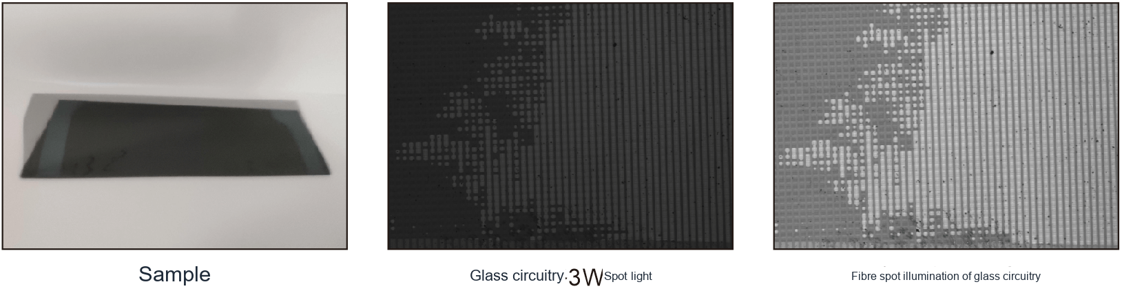
What inspection variables should be evaluated?
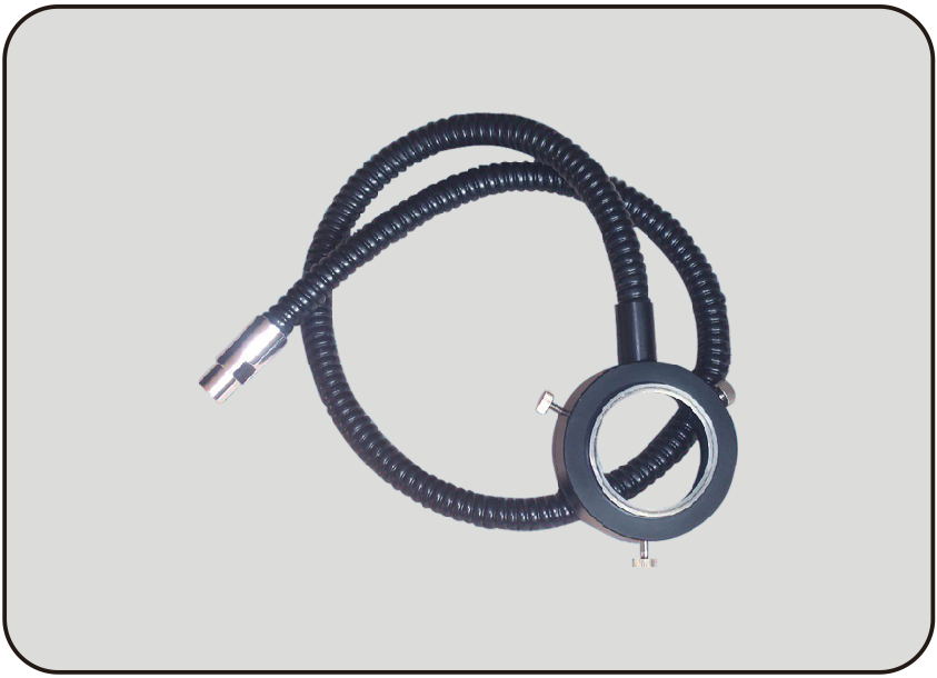
Line, ring and spot fibre heads produce different coverage. Choose by inspection area as well as interface compatibility.
What lighting geometry fits this inspection task?
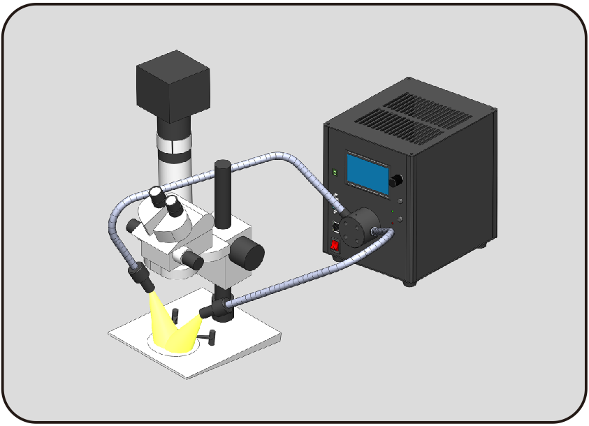
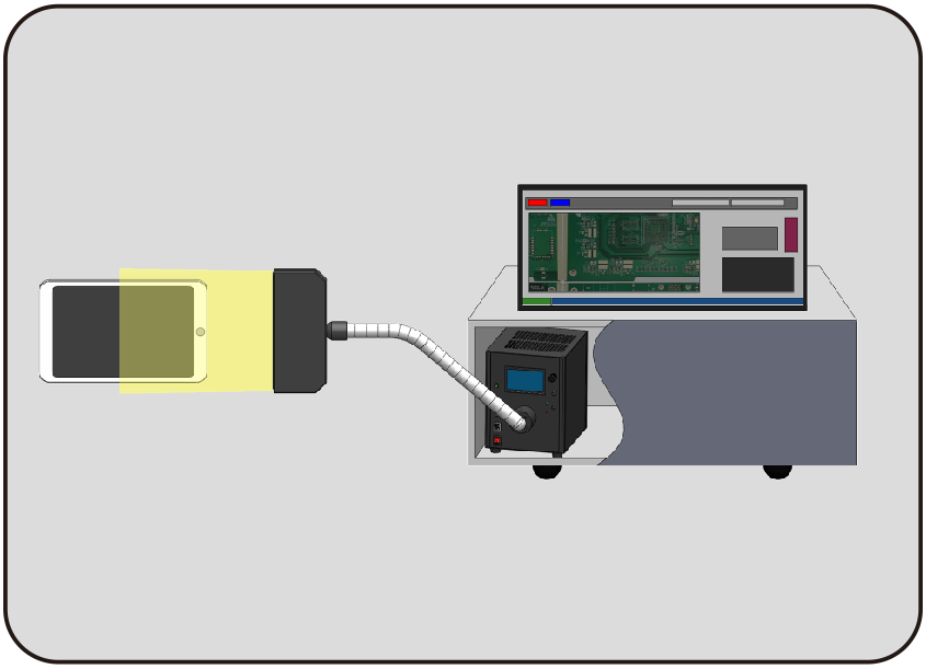
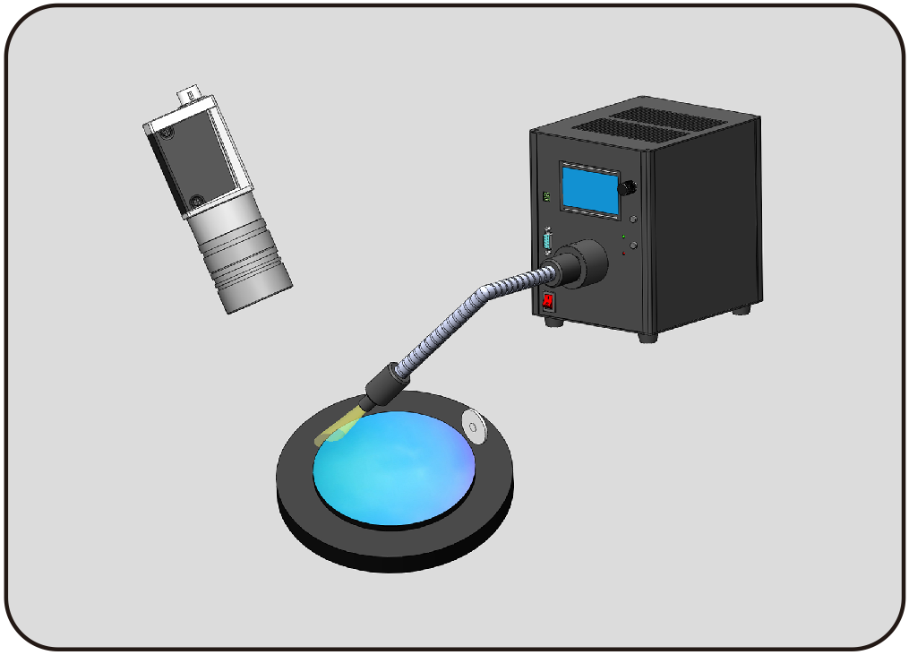
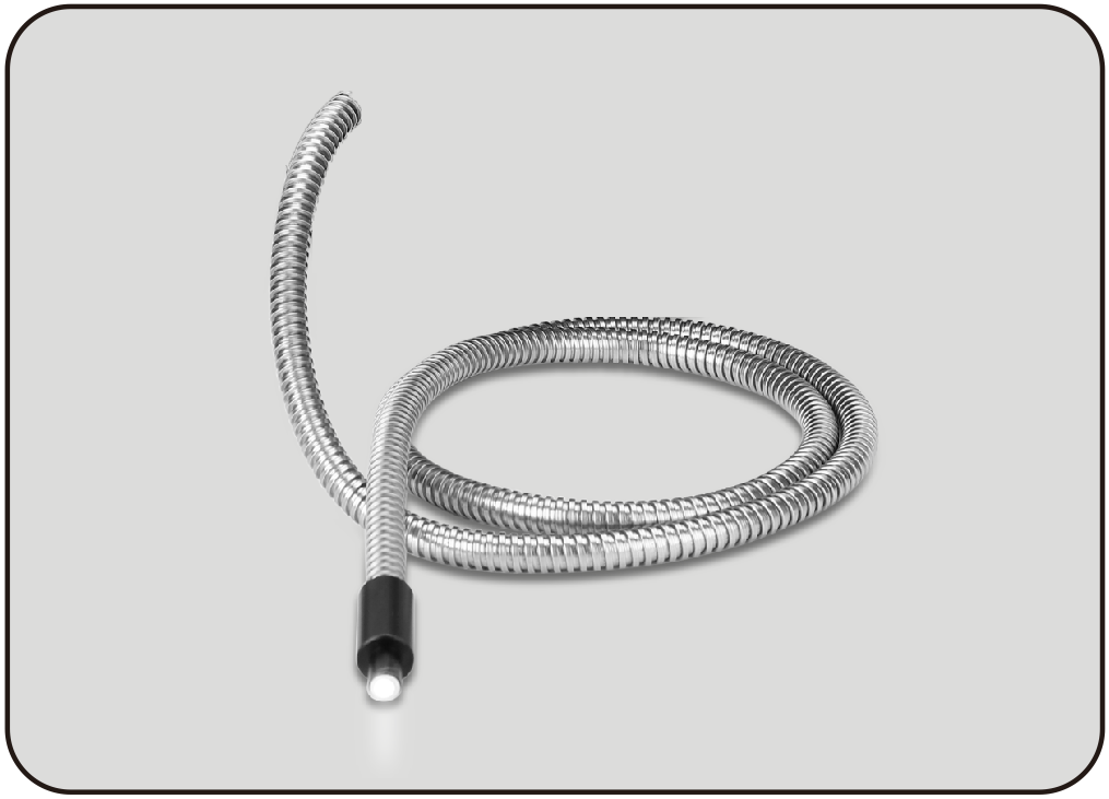
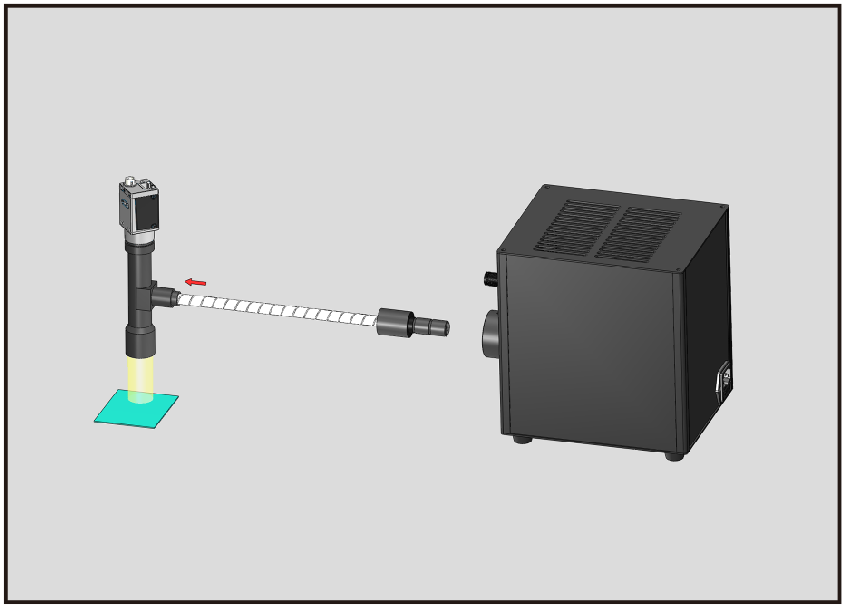
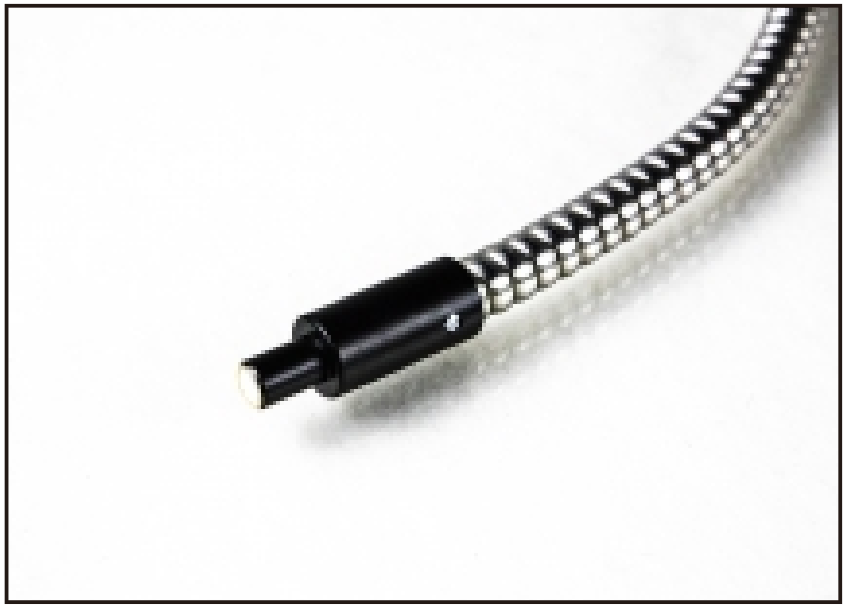
A fibre system separates the light source from its output. Match the source interface, guide diameter, numerical aperture and output geometry. Spot, line and ring guides suit different spaces; coupling and bend radius affect the light reaching the sample.
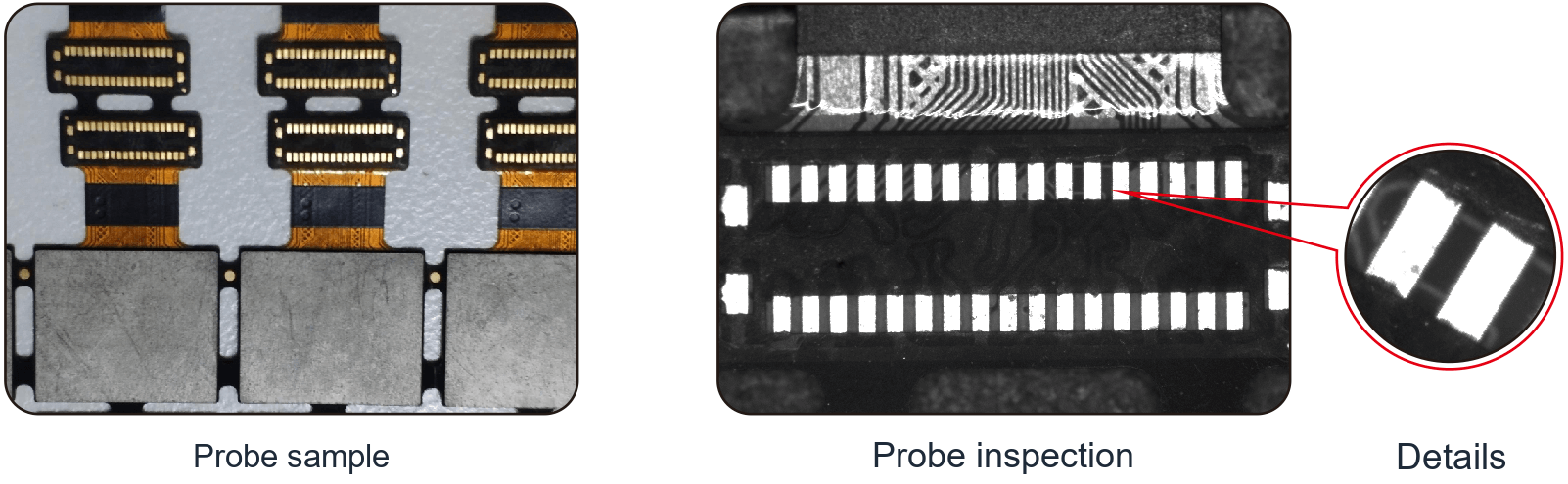
For comparisons, use the same guide, working distance and camera settings. Check connector cleanliness, mounting and temperature. Source output is not the same as illuminance on the workpiece. Judge the complete optical path by usable contrast and exposure margin.
Related product family?
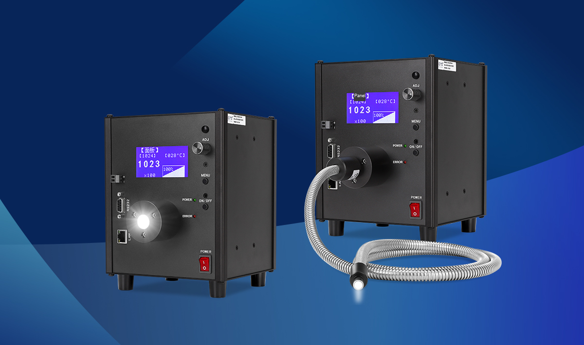
LXV-2SLG
Bring light into compact spaces with a fiber guide.
Communication: RS232/LAN
Light output ports: 1
Compatible bundle diameter: Bundle diameter Φ6-14mm
Beam angle: Full angle 30°
Before choosing a configuration?
For selection, specify the field of view, smallest target feature, height variation, cycle time and installation space. Use the specific product page and drawing to verify electrical ratings, dimensions and compatibility.
Selecting an output shape?
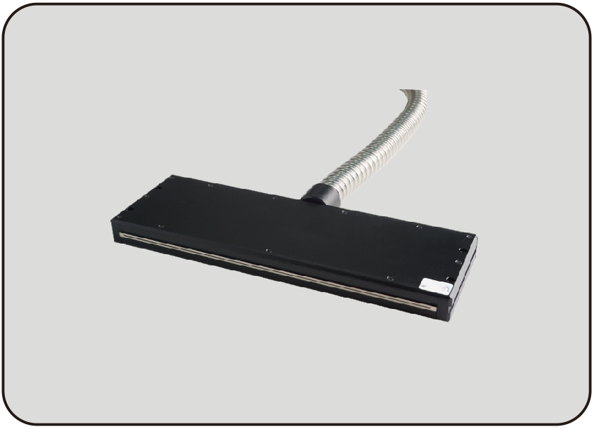
A fibre illuminator can feed different output geometries, including spots, lines and rings. Choose the output from the inspection region and access constraints. The guide's aperture and coupling influence how much light reaches that shape.
Measure the footprint at the working distance and check uniformity with the camera. Confirm the bend radius and output mounting requirements. Reassess exposure whenever the guide, coupling optics or output geometry changes.
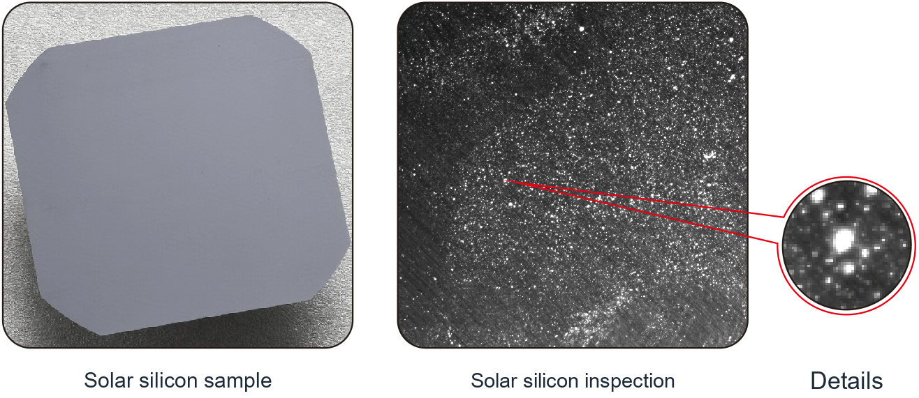
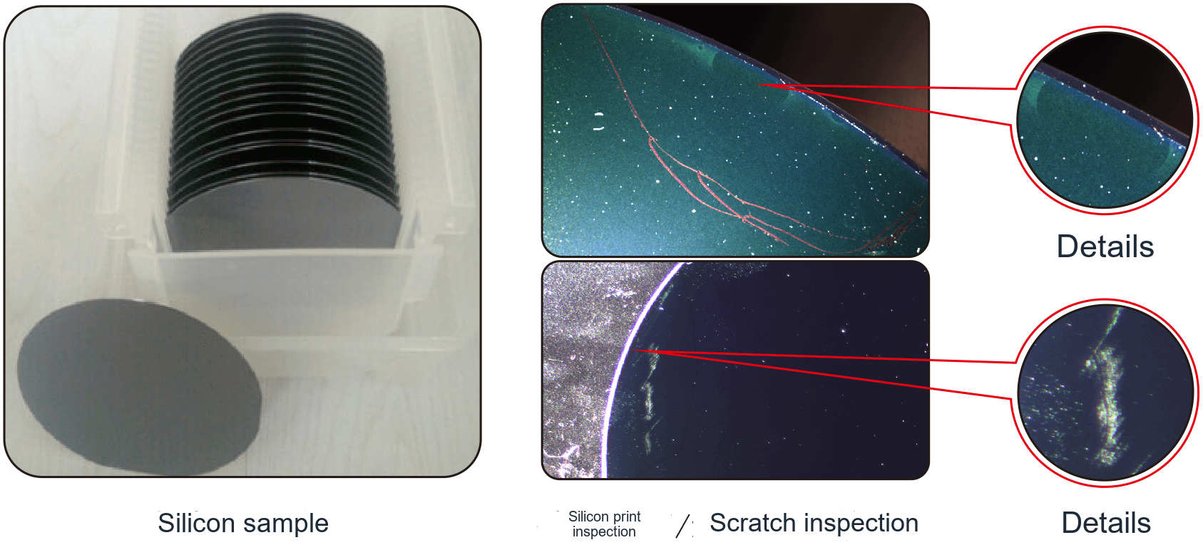
What do the optical setup and sample images show?