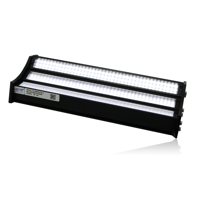
Three-angle bar light for scratches with changing direction
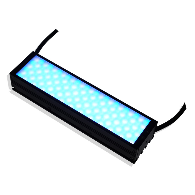
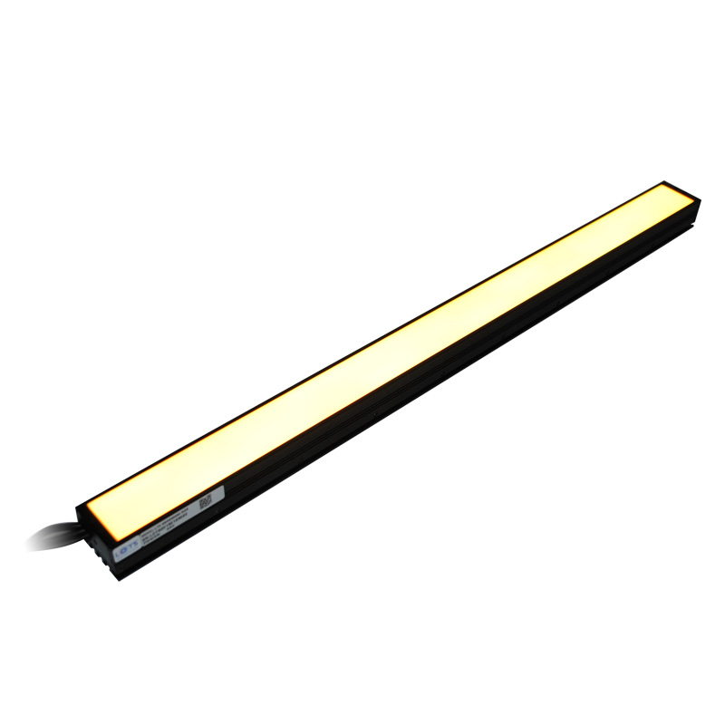
LXV-2BRMU210-W combines three white bar emitters in one 230 × 85 × 60 mm housing. Its 15°, 30° and 50° illumination directions can be balanced independently so scratches remain visible when their orientation changes across flat or curved surfaces.
- Model
- LXV-2BRMU210-W
- Single product-specific design
- Boundary
- 230 × 85 × 60 mm
- Complete housing
- Supply
- 24 V
- 15 W
- Illumination axes
- 15° / 30° / 50°
- Three adjustable directions
Plane-surface scratches
Use the three directions to reveal scratches that do not share one fixed orientation.
Arc-surface scratches
Combine the oblique fields around local changes in surface slope.
Changing defect direction
Adjust each bar contribution when the scratch direction varies through the field.
Directional-contrast validation
Compare the three responses on the real material before fixing exposure.
How the optical structure solves the inspection problem
Review the product-specific optical behavior, confirmed values and technical graphics together before selecting the final configuration.
- Three bar emitters
- Three linear sources are integrated into the curved section of one housing.
- 15° / 30° / 50° axes
- The end-view drawing identifies the three distinct irradiation directions.
- Independent brightness balance
- Each bar can be adjusted so one incident direction does not dominate the result.
- Elongated coverage
- The 230 mm housing supports a long inspection path while retaining three-angle illumination.
Select from the actual optical, mechanical and electrical requirement
Do not select a custom light from appearance alone. Confirm target, contrast, field, interfaces and load together.
- 1
Map scratch directions
Record every defect orientation that must remain visible.
- 2
Fit surface geometry
Confirm the 15°, 30° and 50° fields reach the target across its flat or curved profile.
- 3
Tune the three bars
Balance each direction on the production material and preserve usable camera exposure.
- 4
Confirm envelope and load
Reserve the 230 × 85 × 60 mm housing and provide 24 V / 15 W capacity.
Read the product model pattern
LXV-2BRMU210-W- LXV
- Product prefix
- 2BRMU
- Multiple-angle bar-light family
- 210
- Length class
- W
- White output
LXV-2BRMU210-W model range
Values remain attached to their own model and are not transferred between designs.
| Model | Output | Boundary | Irradiation axes | Voltage | Power |
|---|---|---|---|---|---|
| LXV-2BRMU210-W | White | L230 × W85 × H60 mm | 15° / 30° / 50° | 24 V | 15 W |
Release the exact product drawing with the complete inspection station
Dimensions, openings, mounting, channels and thermal clearances belong to the selected product only.
- 01
Place the 230 mm long housing so all three illuminated lines cover the inspected path.
- 02
Use the end view to align the 15°, 30° and 50° directions with the surface and camera line of sight.
- 03
Reserve the complete 85 × 60 mm cross-section and keep the three emitting faces unobstructed.
- 04
Provide accessible adjustment for each bar so brightness can be balanced during commissioning.
- 05
Route the supply cable clear of the optical fields and moving equipment; confirm the connector and cable length before fixture release.
- 06
Provide 24 V / 15 W capacity, then validate scratch contrast, exposure and housing temperature at production duty.
Confirm design values and real inspection performance together
- Target, defect and required contrast
- Camera, lens, field and working distance
- Exact model voltage, power and channels
- Boundary, mounting, cable and cooling clearance