Second-generation flat dome illumination for reflective surfaces across high and low working distances
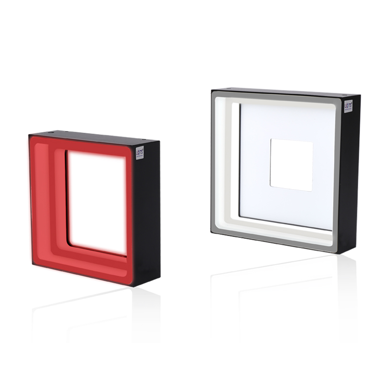
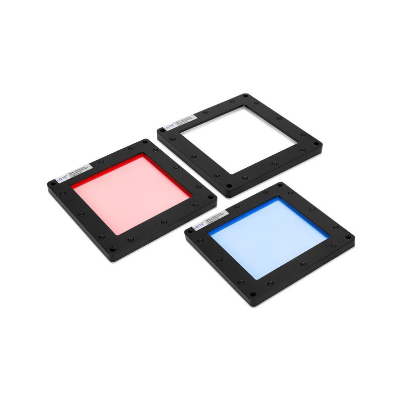
LXV-2LFX combines a printed light-guide plate with flat-dome diffusion to deliver coaxial and dome-style shadowless illumination from an 11.5 mm panel. The source documents a wide usable working-distance range, no visible dot pattern or moiré ripple, high transmission and uniformity, and output five times brighter than the earlier LFX series.
- Standard sizes
- 5
- 50 / 75 / 100 / 150 / 200 mm emitting fields
- Supply
- 24 V
- Every standard model
- Power range
- 6.3–43.7 W
- Exact value depends on size and colour
- Panel height
- 11.5 mm
- All five mechanical drawings
- Documented comparison
- 5× LFX
- Source-series brightness statement
Reflective-bag characters
Reduce concentrated glare so printed characters remain readable.
Metal-can production dates
Combine broad diffuse coverage with coaxial-style reflection control for date inspection.
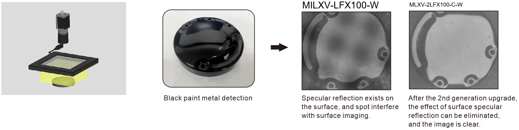
Black-painted metal
Suppress surface specular reflection and remove spot interference from the captured image.
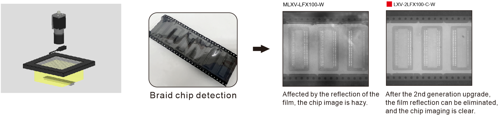
Braid chips under film
Reduce film reflection so the chip pattern is clearer.
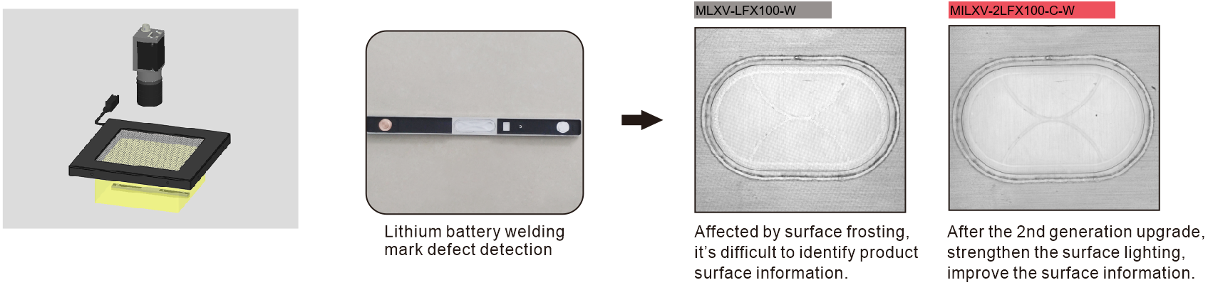
Lithium-battery welding marks
Strengthen surface information that is otherwise obscured by frosting.
Concave and convex patterns
Cover reflective relief with a wide, uniform field without stacking two light housings.
Working-distance response, field uniformity, light-path construction and three application comparisons
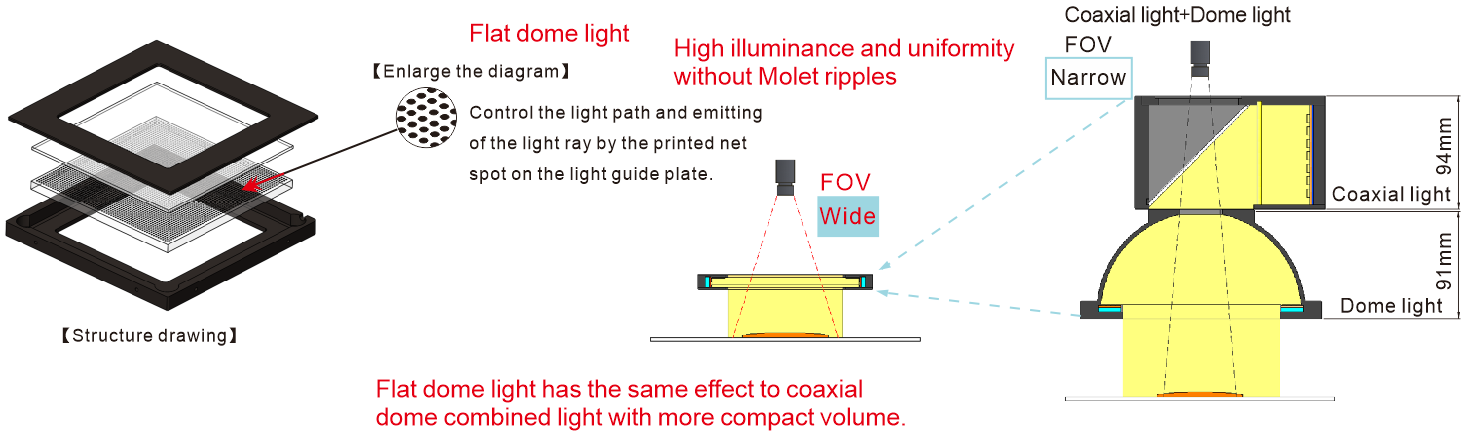
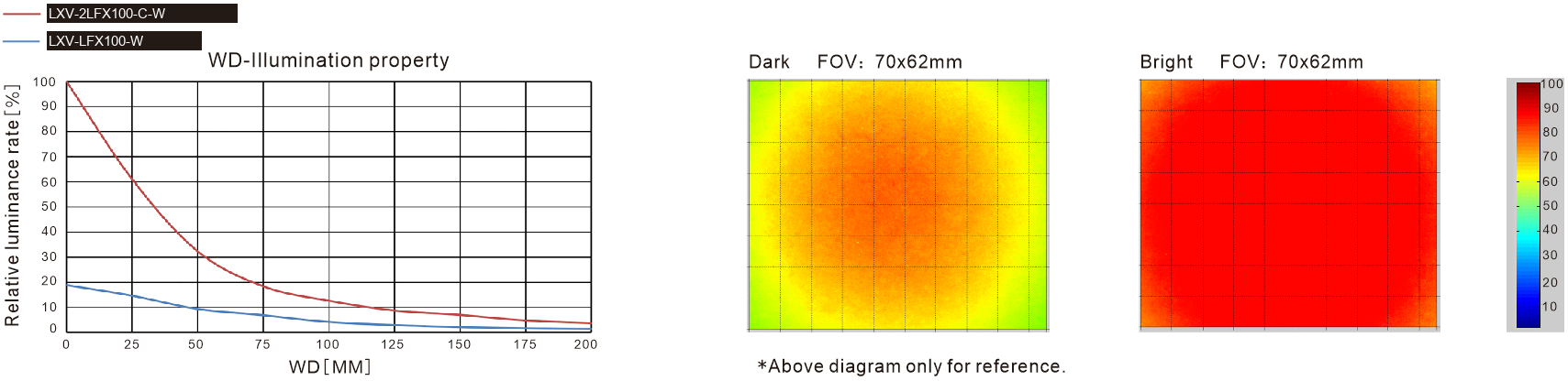
The PDF separates optical evidence from application evidence. LXV-2LFX100-C-W is compared with LXV-LFX100-W in the working-distance curve and in three real inspection chains. Each chart, workpiece and result remains attached to its stated model and purpose.
LXV-2LFX100-C-W optical reference
Flat-dome construction and compact light path
Black-painted metal · LXV-2LFX100-C-W versus LXV-LFX100-W
Braid-chip inspection through reflective film
Lithium-battery welding-mark defect inspection
Configurable flat-panel body
- Optical and application model
- LXV-2LFX100-C-W
- Earlier-series reference
- LXV-LFX100-W
- Uniformity field
- 70 × 62 mm
- Working-distance chart
- 0–200 mm
- Documented improvement
- No dot pattern or moiré ripple
- Light-guide method
- Printed net spots control the light path
- Panel advantage
- Coaxial and dome effect in one compact housing
Choose emitting field, spectrum, load and working distance as one verified configuration
The source coding diagram prints LXV-2LFX##-R/G/B/W/IR/UV, while all five standard model rows include the -C- segment. This page preserves that source distinction and uses the exact standard-row codes for selection.
The PDF specifies 0–50 °C operation and 20–85% RH without condensation; a 50,000 h reference life when luminance is reduced to 50% of the factory default; one year of free technical support and sample free-rent service. It describes a flexible, bend- and heat-resistant PVC extension cable for use inside equipment and a harder, more abrasion-resistant high-flex extension cable for drag-chain production lines.
- 1
Define field and surface
Measure the reflective area and identify whether glare, film reflection, frosting or relief is hiding the required feature.
- 2
Choose the exact size row
Select 50, 75, 100, 150 or 200 mm only with its own power, mass and drawing number.
- 3
Choose spectrum and controller
Test red, green, blue, 6600 K white or a custom IR/UV wavelength, then match the load to an analog, digital or strobe controller.
- 4
Validate at production distance
Use the 100-C-W curves as reference, then confirm uniformity, contrast, exposure and acceptance limits on the real workpiece.
Read the product model pattern
LXV-2LFX##-C-R/G/B/W/IR/UV- LXV
- Product prefix
- 2LFX
- Flat dome light
- ##
- Length of emitting area
- C
- Present in every standard model-table row
- R/G/B/W/IR/UV
- Colour or wavelength code
LXV-2LFX model and optical selection tables
Each value remains attached to its own model or lens row.
Standard LXV-2LFX models
| Model | Supply | Red power | Green / blue / white power | Weight | Drawing | Common |
|---|---|---|---|---|---|---|
| LXV-2LFX50-C | 24 V | 6.3 W | 12.5 W | 204 g | 1 | Y |
| LXV-2LFX75-C | 24 V | 12.5 W | 12.5 W | 296 g | 2 | Y |
| LXV-2LFX100-C | 24 V | 12.5 W | 18.7 W | 434 g | 3 | Y |
| LXV-2LFX150-C | 24 V | 25.0 W | 31.2 W | 752 g | 4 | Y |
| LXV-2LFX200-C | 24 V | 31.2 W | 43.7 W | 1090 g | 5 | Y |
Spectrum, control and configurable options
| Item | Source specification | Selection note |
|---|---|---|
| Visible spectrum | Red 620–630 nm · Green 525–530 nm · Blue 465–470 nm · White 6600 K | Power remains model and colour dependent |
| Adapted controllers | Analog / digital / strobe controller | Match voltage, load and operating mode to the exact model |
| Custom wavelengths | UV and IR can be customised | Validate response and application safety |
| Configurable construction | Length and width · colour / colour temperature · cable length · installation method | Treat a custom build as its own verified configuration |
| Source remark | High clarity and high brightness | Applies to the documented 2LFX series |
Mechanical envelope by model
| Model | Outer size | Reference size | Emitting field | Height | Mounting / lead |
|---|---|---|---|---|---|
| LXV-2LFX50-C | 90 × 90 mm | 77 × 77 mm | 50 × 50 mm | 11.5 mm | 4-Ø3.2 through holes · 500 mm lead |
| LXV-2LFX75-C | 115 × 115 mm | 102 × 102 mm | 75 × 75 mm | 11.5 mm | 4-Ø3.2 through holes · 500 mm lead |
| LXV-2LFX100-C | 140 × 140 mm | 127 × 127 mm | 100 × 100 mm | 11.5 mm | 4-Ø3.2 through holes · 500 mm lead |
| LXV-2LFX150-C | 190 × 190 mm | 177 × 177 mm | 150 × 150 mm | 11.5 mm | 4-Ø3.2 through holes · 500 mm lead |
| LXV-2LFX200-C | 240 × 240 mm | 227 × 227 mm | 200 × 200 mm | 11.5 mm | 4-Ø3.2 through holes · 500 mm lead |
Centre the camera above the aperture and preserve the complete 11.5 mm panel envelope
The complete five-model drawing is tightly bounded and shown at its natural ratio. Every outer size, emitting field, through-hole callout, side profile and 500 mm lead remains visible without splitting a drawing across cards.
- 01
Match the exact model to drawing 1–5 and its own electrical row.
- 02
Centre the camera sight line over the emitting opening and keep panel, target and image plane aligned.
- 03
Reserve access to all four Ø3.2 through holes, the side connector, 500 mm lead and cable bend radius.
- 04
Validate field coverage, reflection suppression, exposure, controller capacity and service access before release.
Verify model, optical result and mechanical fit together
- Exact product model and colour
- Working distance and camera field
- Voltage, power and controller
- Mounting, cable and thermal clearance