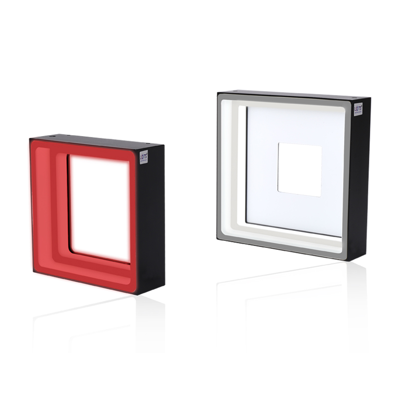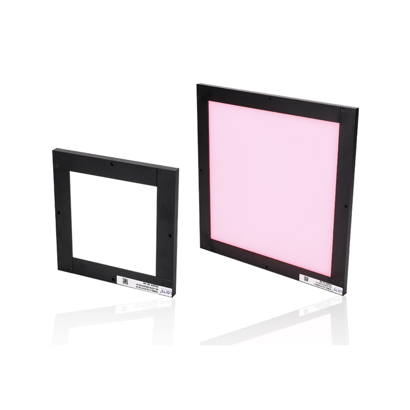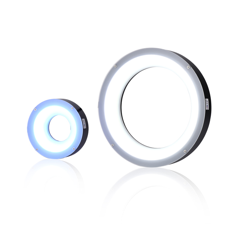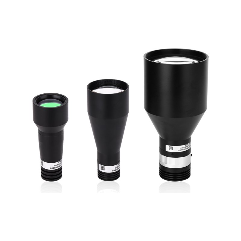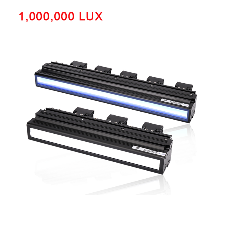
| Model | Color | Dimension | Voltage | Power |
|---|---|---|---|---|
| LXV-2LINS100-R/BGW | Red / Blue / Green / White | L100xW53xH121.5(mm) | 24V | 36W |
| LXV-2LINS140-R/BGW | Red / Blue / Green / White | L140xW53xH121.5(mm) | 24V | 54W |
| LXV-2LINS180-R/BGW | Red / Blue / Green / White | L180xW53xH121.5(mm) | 24V | 72W |
| LXV-2LINS220-R/BGW | Red / Blue / Green / White | L220xW53xH121.5(mm) | 24V | 90W |
| LXV-2LINS260-R/BGW | Red / Blue / Green / White | L260xW53xH121.5(mm) | 24V | 108W |
| LXV-2LINS300-R/BGW | Red / Blue / Green / White | L300xW53xH121.5(mm) | 24V | 126W |
| LXV-2LINS340-R/BGW | Red / Blue / Green / White | L340xW53xH121.5(mm) | 24V | 144W |
| LXV-2LINS380-R/BGW | Red / Blue / Green / White | L380xW53xH121.5(mm) | 24V | 162W |
| LXV-2LINS420-R/BGW | Red / Blue / Green / White | L420xW53xH121.5(mm) | 24V | 180W |
| LXV-2LINS460-R/BGW | Red / Blue / Green / White | L460xW53xH121.5(mm) | 24V | 198W |
| LXV-2LINS500-R/BGW | Red / Blue / Green / White | L500xW53xH121.5(mm) | 24V | 216W |
| LXV-2LINS780-R/BGW | Red / Blue / Green / White | L780xW53xH121.5(mm) | 24V | 342W |
| LXV-2LINS900-R/BGW | Red / Blue / Green / White | L900xW53xH121.5(mm) | 48V | 432W |
| LXV-2LINS1066-R/BGW | Red / Blue / Green / White | L1066xW53xH121.5(mm) | 48V | 432W |
| LXV-2LINS1200-R/BGW | Red / Blue / Green / White | L1200xW53xH121.5mm) | 48V | 504W |
| LXV-2LINS1300-R/BGW | Red / Blue / Green / White | L1300xW53xH121.5mm) | 48V | 540W |
| LXV-2LINS1500-R/BGW | Red / Blue / Green / White | L1500xW53xH121.5mm) | 48V | 648W |
| LXV-2LINS1600-R/BGW | Red / Blue / Green / White | L1600xW53xH121.5mm) | 48V | 648W |
| LXV-2LINS1720-R/BGW | Red / Blue / Green / White | L1720xW53xH121.5mm) | 48V | 720W |
| LXV-2LINS1916-R/BGW | Red / Blue / Green / White | L1916xW53xH121.5mm) | 48V | 756W |
| LXV-2LINS2700-R/BGW | Red / Blue / Green / White | L2700xW53xH121.5(mm) | 48V | 1080W |
| * UV & IR light can be customized as required. | - | - | - | - |
IMAGING COMPARISON
Application Effect Analysis
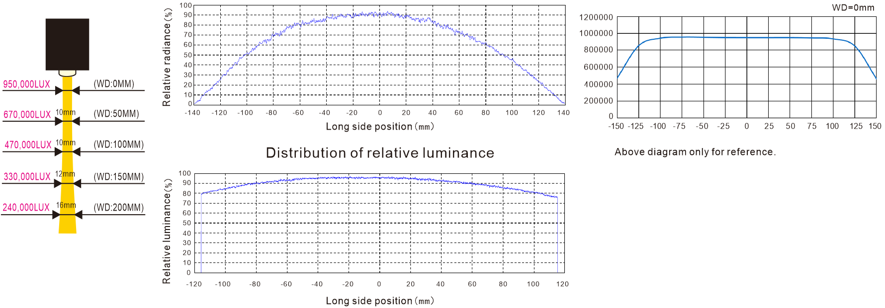
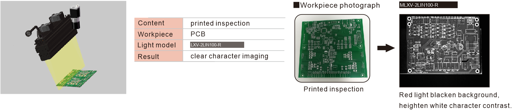
Real-world inspection imaging comparison — demonstrating the contrast and uniformity advantages of LXV-2LINS.
OPTICAL DESIGN & NAMING
Optical Diagram & Model Naming Convention
Model Naming Convention
Vector DiagramDIRECT ENQUIRY
Get a Customized Quotation
Need specific dimensions, custom wavelength LED combinations, or special cabling? Our optical engineering and sales offices are ready to assist.
Sales Email: info@luxmv.com
Response SLA: Under 4 Hours (Business Days)
Free Optical Simulation
Send us your target workpiece samples. We will test them in our R&D lighting darkrooms and supply a selection report completely free.
Request Technical Quotation
Our optical engineering sales team responds to all corporate requests within 4 hours.