Collimated backlight for accurate contour and diameter measurement
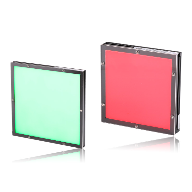
LXV-4PFT and LXV-3PFT use parallel film with an ultra-thin SMD LED backlight to reduce virtual borders around transmitted silhouettes. Twenty-four 24 V models cover square emitting fields from 30 × 30 mm to 200 × 200 mm for metal, glass, ceramic and threaded-part measurement.
- Standard models
- 24
- 14 LXV-4PFT and 10 LXV-3PFT rows
- Emitting fields
- 30 × 30–200 × 200 mm
- Exact model dependent
- Supply
- 24 V
- Every standard model
- Power
- 1.1–37.8 W
- Colour and model dependent
- Optical option
- Single or double film
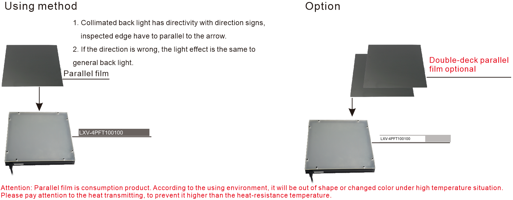
- Double-deck parallel film is optional
Metal-column diameter
Reduce the virtual border around the projected cylindrical edge before dimensional measurement.
Glass-bottle diameter
Use transmitted collimated illumination to define the bottle outline.
Ceramic-column diameter
Form a controlled silhouette around cylindrical ceramic parts.
Screw-thread contour
Reveal the thread profile as a dark, sharply bounded outline for contour inspection.
Measured output, orientation rules and contour-inspection evidence
Searchable text carries the operating conditions and conclusions. The retained images are bounded optical fields, workpieces, results and film-construction objects rather than complete catalogue pages.
LXV-4PFT100100-W optical reference
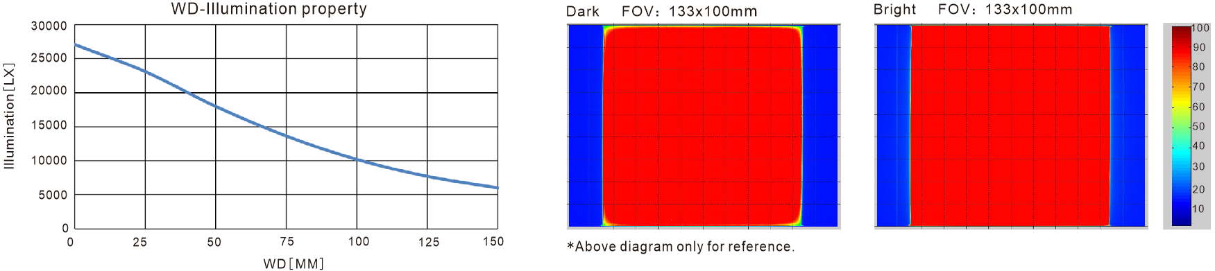
The relative-luminance curve is referenced to WD 0 mm. Dark- and bright-field examples each retain a 133 × 100 mm field of view and the original 10 mm scale.
Screw-thread contour inspection
The documented arrangement uses a camera above the screw and an LXV-4PFT5050-W below it. The resulting silhouette presents an obvious black edge without a virtual border, making the thread contour easier to inspect.
Metal-column edge comparison
The left half uses a standard backlight and is brighter but produces a wider virtual border. The collimated PFT result at right has lower apparent luminance and a narrower virtual border, supporting higher edge-position precision.
Parallel-film orientation and optional double layer
Collimated output is directional: install the panel so the inspected edge is parallel to its direction arrow. A wrong orientation behaves like a general backlight. A double-deck parallel-film option is available when the application requires it.
Optical and application reference conditions
Values and conclusions below remain tied to the stated reference model or comparison.
| Reference | Condition | Recorded information |
|---|---|---|
| LXV-4PFT100100-W | WD 0–200 mm | Relative luminance uses WD 0 mm as 100%; the plotted value is approximately 42% at WD 200 mm. |
| LXV-4PFT100100-W | Dark FOV | 133 × 100 mm field; 10 mm scale. |
| LXV-4PFT100100-W | Bright FOV | 133 × 100 mm field; 10 mm scale. |
| LXV-4PFT5050-W | Screw contour | Obvious black edge without a pronounced virtual border. |
| Standard backlight vs collimated PFT | Metal-column diameter | The PFT result reduces the virtual border used for edge-position measurement. |
- Optical structure
- Parallel film over an ultra-thin SMD LED panel
- Required orientation
- Inspected edge parallel to the direction arrow
- Optional construction
- Double-deck parallel film
- Film care
- Protect the consumable film from excessive transmitted heat that can deform or discolour it
Select one exact field, body family and electrical row
The 14 LXV-4PFT and 10 LXV-3PFT rows differ in power, weight, envelope and drawing group. Keep all values attached to the selected model and colour.
- 1
Define the measured contour
Record the complete silhouette, edge direction, tolerance and required field.
- 2
Choose 4PFT or 3PFT
Compare the available field, body thickness and mounting pattern rather than transferring dimensions between families.
- 3
Select field and colour
Choose an emitting area that contains the full target and use the stated R or G/B/W power.
- 4
Validate before release
Test working distance, arrow orientation, lens aperture and the actual workpiece before fixing the exact model.
Read the product model pattern
LXV-[4PFT|3PFT][length][width]-[R/G/B/W/IR/UV]- LXV
- Product prefix
- 4PFT / 3PFT
- Collimated backlight family
- First dimension
- Emitting length in millimetres
- Second dimension
- Emitting width in millimetres
- R / G / B / W / IR / UV
- Colour or wavelength code
LXV-4PFT complete standard range
Power is listed separately for red and for green/blue/white. UV and IR can be customised.
| Model | Voltage | Red power | G/B/W power | Emitting area | Overall size | Weight | Drawing |
|---|---|---|---|---|---|---|---|
| LXV-4PFT3030 | 24 V | 1.1 W | 1.1 W | 30 × 30 mm | 44 × 44 × 19 mm | 95 g | 4PFT-1 |
| LXV-4PFT5050 | 24 V | 2.2 W | 3.7 W | 50 × 50 mm | 64 × 64 × 19 mm | 118 g | 4PFT-2 |
| LXV-4PFT6060 | 24 V | 4.8 W | 4.8 W | 60 × 60 mm | 74 × 74 × 19 mm | 142 g | 4PFT-2 |
| LXV-4PFT7070 | 24 V | 4.8 W | 5.3 W | 70 × 70 mm | 84 × 84 × 19 mm | 190 g | 4PFT-2 |
| LXV-4PFT8080 | 24 V | 6.4 W | 8.0 W | 80 × 80 mm | 94 × 94 × 19 mm | 221 g | 4PFT-2 |
| LXV-4PFT9090 | 24 V | 6.4 W | 8.0 W | 90 × 90 mm | 104 × 104 × 19 mm | 304 g | 4PFT-2 |
| LXV-4PFT100100 | 24 V | 9.6 W | 11.1 W | 100 × 100 mm | 114 × 114 × 19 mm | 357 g | 4PFT-3 |
| LXV-4PFT120120 | 24 V | 11.1 W | 14.8 W | 120 × 120 mm | 134 × 134 × 19 mm | 401 g | 4PFT-3 |
| LXV-4PFT130130 | 24 V | 12.7 W | 15.9 W | 130 × 130 mm | 144 × 144 × 19 mm | 456 g | 4PFT-3 |
| LXV-4PFT140140 | 24 V | 12.7 W | 16.9 W | 140 × 140 mm | 154 × 154 × 19 mm | 493 g | 4PFT-3 |
| LXV-4PFT150150 | 24 V | 19.0 W | 23.8 W | 150 × 150 mm | 164 × 164 × 19 mm | 561 g | 4PFT-3 |
| LXV-4PFT160160 | 24 V | 19.0 W | 23.8 W | 160 × 160 mm | 174 × 174 × 19 mm | 605 g | 4PFT-3 |
| LXV-4PFT180180 | 24 V | 21.2 W | 26.4 W | 180 × 180 mm | 194 × 194 × 19 mm | 730 g | 4PFT-3 |
| LXV-4PFT200200 | 24 V | 25.4 W | 34.9 W | 200 × 200 mm | 214 × 214 × 21.5 mm | 846 g | 4PFT-4 |
LXV-3PFT complete standard range
Power is listed separately for red and for green/blue/white. UV and IR can be customised.
| Model | Voltage | Red power | G/B/W power | Emitting area | Overall size | Weight | Drawing |
|---|---|---|---|---|---|---|---|
| LXV-3PFT5050 | 24 V | 2.9 W | 3.6 W | 50 × 50 mm | 67 × 67 × 25 mm | 152 g | 3PFT-1 |
| LXV-3PFT6060 | 24 V | 4.4 W | 5.4 W | 60 × 60 mm | 77 × 77 × 25 mm | 173 g | 3PFT-1 |
| LXV-3PFT7070 | 24 V | 5.8 W | 6.5 W | 70 × 70 mm | 87 × 87 × 25 mm | 201 g | 3PFT-1 |
| LXV-3PFT8080 | 24 V | 6.5 W | 8.7 W | 80 × 80 mm | 97 × 97 × 25 mm | 244 g | 3PFT-1 |
| LXV-3PFT100100 | 24 V | 11.6 W | 14.4 W | 100 × 100 mm | 117 × 117 × 25 mm | 321 g | 3PFT-1 |
| LXV-3PFT110110 | 24 V | 13.0 W | 16.2 W | 110 × 110 mm | 127 × 127 × 25 mm | 374 g | 3PFT-1 |
| LXV-3PFT120120 | 24 V | 13.0 W | 16.2 W | 120 × 120 mm | 137 × 137 × 25 mm | 453 g | 3PFT-1 |
| LXV-3PFT130130 | 24 V | 15.9 W | 19.8 W | 130 × 130 mm | 147 × 147 × 25 mm | 486 g | 3PFT-1 |
| LXV-3PFT150150 | 24 V | 17.3 W | 28.1 W | 150 × 150 mm | 167 × 167 × 25 mm | 587 g | 3PFT-1 |
| LXV-3PFT200200 | 24 V | 30.3 W | 37.8 W | 200 × 200 mm | 217 × 217 × 27 mm | 927 g | 3PFT-2 |
Colour, controller and operating reference
| Item | Standard information | Selection note |
|---|---|---|
| Red | 620–630 nm | Use the exact red-power value for the selected model. |
| Green | 525–530 nm | Use the G/B/W power column. |
| Blue | 465–470 nm | Use the G/B/W power column. |
| White | 6600 K | Use the G/B/W power column. |
| UV / IR | Customisable | Confirm wavelength and electrical load before release. |
| Compatible controller types | Analog / digital / high-power | Match controller capacity to the selected light load. |
| Operating environment | 0–40 °C; 20–85% RH | Non-condensing. |
| Service-life reference | 50,000 h | Time until luminance reaches 50% of the factory-default level. |
| PVC cable | Flexible, bendable and heat-resistant | Intended for routing inside a device. |
| High-flex cable | Harder and more abrasion-resistant | Intended for drag-chain use. |
Install by the exact family drawing and preserve optical direction
Six complete drawing groups cover all 24 models. The 4PFT family uses 19 or 21.5 mm overall thickness; 3PFT uses 25 or 27 mm. Hole count, pitch and body allowance change by group.
- 01
Use only the drawing group assigned to the selected model row.
- 02
Align the inspected edge parallel to the direction arrow and keep the full target inside the emitting field.
- 03
Reserve the 500 mm lead, connector bend and access to the rear M3 mounting holes.
- 04
Control transmitted heat at the film surface and revalidate edge position after final installation.
Mechanical group reference
A and B are emitting dimensions unless the row states fixed values.
| Drawing group | Models | Emitting / overall dimensions | Rear mounting | Body thickness / lead |
|---|---|---|---|---|
| 4PFT-1 | LXV-4PFT3030 | 30 × 30 mm / 44 × 44 mm | 4-M3 depth 4 | 19 mm total; 17 mm body + 2 mm film; 500 mm lead |
| 4PFT-2 | LXV-4PFT5050–9090 | A × B / (A+14) × (B+14) mm | 6-M3 depth 4; pitch A−25 | 19 mm total; 17 mm body + 2 mm film; 500 mm lead |
| 4PFT-3 | LXV-4PFT100100–180180 | A × B / (A+14) × (B+14) mm | 6-M3 depth 4; pitch A−25 | 19 mm total; 17 mm body + 2 mm film; 500 mm lead |
| 4PFT-4 | LXV-4PFT200200 | 200 × 200 mm / 214 × 214 mm | 10-M3 depth 4; 175 mm internal reference | 21.5 mm total; 17 mm body + 2 mm film; 500 mm lead |
| 3PFT-1 | LXV-3PFT5050–150150 | A × B / (A+17) × (B+17) mm | 4-M3 depth 4; pitch A−25 | 25 mm total; 23 mm body; 500 mm lead |
| 3PFT-2 | LXV-3PFT200200 | 200 × 200 mm / 217 × 217 mm | 6-M3 depth 4; 150 mm internal reference | 27 mm total; 25 mm body; 500 mm lead |
LXV-4PFT mechanical drawings
The 30 mm model, 50–90 mm group, 100–180 mm group and 200 mm model retain their complete independent dimension objects.
LXV-3PFT mechanical drawings
The 50–150 mm group and 200 mm model use distinct body thicknesses and mounting arrangements.
Verify optical result, exact model and installation together
- Target, feature and required contrast
- Field, direction and working distance
- Exact voltage, power and controller load
- Mounting, cable and thermal clearance