Four-sided adjustable bar illumination for marks, codes, solder joints and curved workpieces
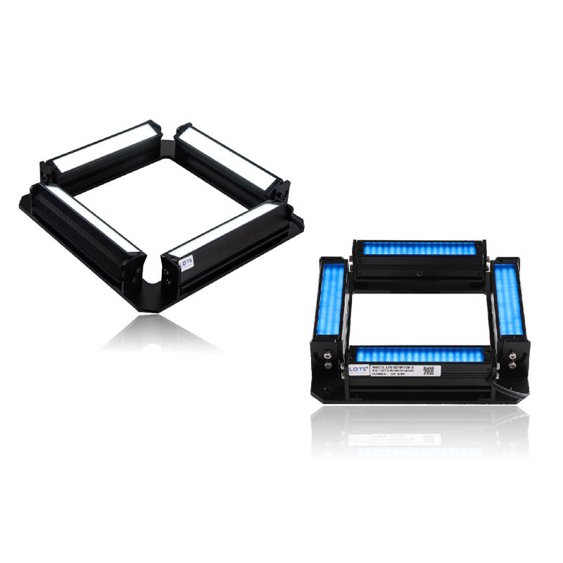
LXV-4BRM combines four independently illuminated bar lights around a rectangular opening. Each side can be adjusted to match the target geometry, so one assembly can provide multi-direction illumination for PCB and IC inspection, solder-joint checks, mark positioning, packaging barcodes and spherical or mechanical workpieces.
- Standard models
- 11
- Six square and five rectangular frames
- Supply
- 24 V
- Every documented model row
- Power range
- 2.9–93.6 W
- Exact model and colour group dependent
- Optical reference
- LXV-4BRM200-W
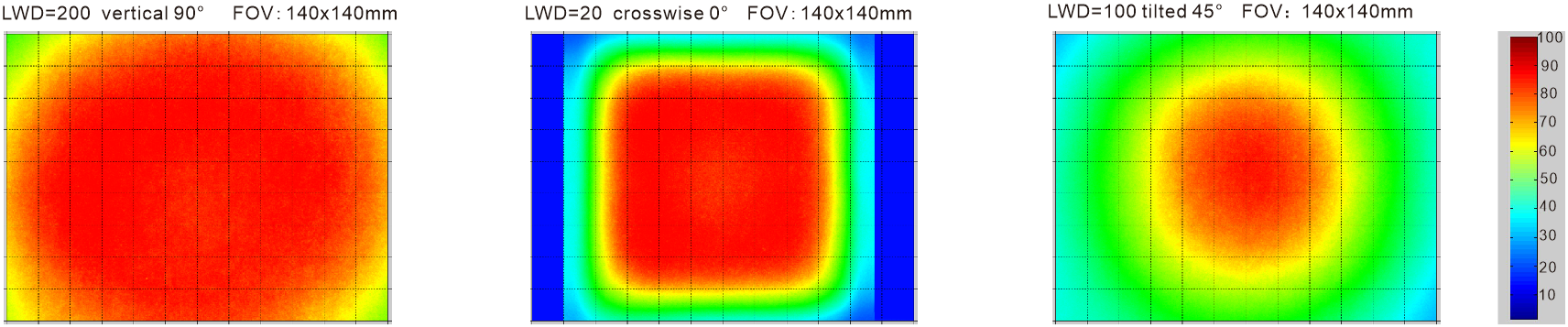
- FOV 140 × 140 mm · three documented light directions
- Application reference
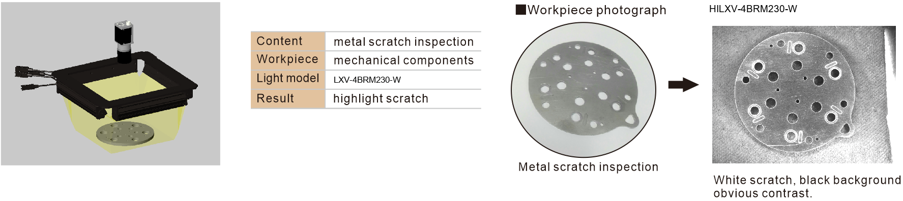
- LXV-4BRM230-W
- Metal mechanical-component scratch inspection
PCB and IC inspection
Aim the four sides independently so component outlines, marks and solder features receive useful light from multiple directions.
Solder-joint and mark positioning
Adjust bar angle and side output to reveal shape changes while keeping the camera view clear through the central opening.
Packaging barcode illumination
Surround the code area with directional light to reduce one-sided shadowing and preserve printed edge contrast.
Spherical and mechanical workpieces
Use the four-sided geometry to illuminate curved parts; the documented metal example makes a scratch appear white against a black background.
Three illumination directions and complete metal-scratch inspection evidence
The PDF tests LXV-4BRM200-W over the same 140 × 140 mm field in three configurations: vertical illumination at LWD 200 mm, crosswise illumination at LWD 20 mm and 45° tilted illumination at LWD 100 mm. The separate LXV-4BRM230-W application is rebuilt as a complete arrangement–workpiece–result sequence.
LXV-4BRM200-W optical reference · FOV 140 × 140 mm
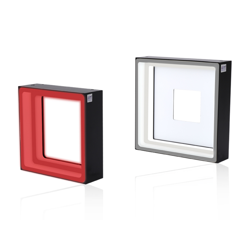
Configurable four-bar construction
Metal scratch inspection · LXV-4BRM230-W
- Optical model
- LXV-4BRM200-W
- Vertical 90° field
- LWD 200 mm · FOV 140 × 140 mm
- Crosswise 0° field
- LWD 20 mm · FOV 140 × 140 mm
- Tilted field
- 45° · LWD 100 mm · FOV 140 × 140 mm
- Application model
- LXV-4BRM230-W
- Documented result
- Highlighted scratch · white scratch · black background · obvious contrast
Select one complete frame row, then keep its power, mass and drawing together
The 11 standard models all use 24 V, but power, mass, frame proportions, emitting width, mounting pattern and common-build status change by row. Power is separately specified for red and for green, blue or white output.
Source fidelity note: all model, power, mass, wavelength, environment, service and mechanical values above are transcribed from the supplied 2025 light-source PDF. The optical maps are reference evidence for LXV-4BRM200-W; the scratch result is a separate LXV-4BRM230-W example. Validate the selected geometry and lighting result on the real workpiece before release.
- 1
Define the illuminated opening
Record target width and height, camera field, working distance, required side directions and available machine envelope.
- 2
Choose square or rectangular frame
Use a square 96–290 model or one of the five rectangular size codes without transferring dimensions between drawings.
- 3
Choose colour and control
Test red, green, blue, white or a confirmed custom UV/IR wavelength, then decide whether independent or multi-area side control is needed.
- 4
Validate the complete system
Match the exact row to an analog, digital or high-power controller and confirm contrast, side balance, exposure, thermal duty and acceptance criteria on production samples.
Read the product model pattern
LXV-4BRM##-R/G/B/W/IR/UV- LXV
- Product prefix
- 4BRM
- Four-sided combined bar-light family
- ##
- Length of side or rectangular size code
- R/G/B/W/IR/UV
- Colour or wavelength code
LXV-4BRM model and optical selection tables
Each value remains attached to its own model or lens row.
Standard LXV-4BRM models
| Model | Supply | Power · R | Power · G/B/W | Weight | Drawing | Common |
|---|---|---|---|---|---|---|
| LXV-4BRM96 | 24 V | 2.9 W | 4.4 W | 343 g | 1 | Y |
| LXV-4BRM130 | 24 V | 5.8 W | 8.7 W | 469 g | 2 | Y |
| LXV-4BRM160 | 24 V | 8.7 W | 13.0 W | 620 g | 3 | Y |
| LXV-4BRM200 | 24 V | 11.6 W | 17.3 W | 759 g | 4 | Y |
| LXV-4BRM230 | 24 V | 14.4 W | 21.6 W | 894 g | 5 | Y |
| LXV-4BRM290 | 24 V | 20.2 W | 30.3 W | 1329 g | 6 | N |
| LXV-4BRM204154 | 24 V | 9.4 W | 13.7 W | 665 g | 7 | N |
| LXV-4BRM285235 | 24 V | 26.0 W | 43.2 W | 1403 g | 8 | N |
| LXV-4BRM330260 | 24 V | 32.4 W | 54.0 W | 1662 g | 9 | N |
| LXV-4BRM400360 | 24 V | 24.5 W | 36.8 W | 1700 g | 10 | N |
| LXV-4BRM532382 | 24 V | 56.2 W | 93.6 W | 3100 g | 11 | N |
Spectrum, control, environment and service
| Item | PDF specification | Engineering use |
|---|---|---|
| Visible output | Red 620–630 nm · Green 525–530 nm · Blue 465–470 nm · White 6600 K | Keep colour and power from the same exact model row |
| Custom wavelengths | UV and IR can be customised | Confirm wavelength, irradiance and safety before release |
| Controller types | Analog / digital / high-power controller | Match operating mode, side control and total connected load |
| Configurable construction | Bar quantity · length and width · shape · colour / colour temperature · combined light · cable length · multi-area control · installation | Treat each custom build as its own verified configuration |
| Operating environment | 0–40 °C · 20–85% RH without condensation | Verify machine conditions and cooling |
| Reference life | 50,000 h when luminance is reduced to 50% of factory default | PDF reference condition, not a universal guarantee |
| Support | One year of free technical support · sample free-rent service | Confirm current commercial terms separately |
| PVC extension cable | Flexible, bend- and heat-resistant; intended inside equipment | Use for stationary in-equipment routing |
| High-flex extension cable | Harder and more abrasion-resistant; intended for drag-chain production lines | Use for repeated-motion routing |
Mechanical dimensions by drawing
| Drawing / model | Outer frame | Intermediate / inner frame | Emitting area | Opening | Bar section | Mounting |
|---|---|---|---|---|---|---|
| 1 · LXV-4BRM96 | 96 × 96 mm | 70 / 46 mm | 30 × 30 mm | — | 16 mm emitting · 37 × 4 mm | 4-M4 depth 4 |
| 2 · LXV-4BRM130 | 130 × 130 mm | 105 / 78 mm | 60 × 60 mm | — | 16 mm emitting · 37 × 4 mm | 4-M4 depth 4 |
| 3 · LXV-4BRM160 | 160 × 160 mm | 135 / 108 mm | 90 × 90 mm | — | 16 mm emitting · 37 × 4 mm | 4-M4 depth 4 |
| 4 · LXV-4BRM200 | 200 × 200 mm | 175 / 148 mm | 120 × 120 mm | 100 × 100 mm | 16 mm emitting · 37 × 4 mm | 8-M4 depth 4 |
| 5 · LXV-4BRM230 | 230 × 230 mm | 205 / 176 mm | 150 × 150 mm | 120 × 120 mm | 16 mm emitting · 37 × 4 mm | 8-M4 depth 4 |
| 6 · LXV-4BRM290 | 290 × 290 mm | 265 / 236 mm | 210 × 210 mm | 150 × 150 mm | 16 mm emitting · 39 × 6 mm | 8-M4 through-hole |
| 7 · LXV-4BRM204154 | 204 × 154 mm | 179 × 129 / 150 × 100 mm | 120 × 75 mm | 100 × 50 mm | 16 mm emitting · 37 × 4 mm | 8-M4 depth 4 reverse |
| 8 · LXV-4BRM285235 | 285 × 235 mm | 244 × 194 / 203 × 153 mm | 175 × 125 mm | 120 × 100 mm | 30 mm emitting · 44 × 4 mm | 8-M4 depth 4 reverse |
| 9 · LXV-4BRM330260 | 330 × 260 mm | 289 × 219 / 248 × 178 mm | 220 × 150 mm | 160 × 120 mm | 30 mm emitting · 44 × 4 mm | 8-M4 depth 4 |
| 10 · LXV-4BRM400360 | 400 × 360 mm | 375 × 335 / 346 × 306 mm | 270 × 240 mm | 210 × 180 mm | 16 mm emitting · 39 × 6 mm | 12-M4 through-hole reverse |
| 11 · LXV-4BRM532382 | 532 × 382 mm | 492 × 342 / 450 × 300 mm | 400 × 255 mm | 320 × 200 mm | 30 mm emitting · 46 × 6 mm | 16-M4 depth 4 reverse |
Preserve the complete four-sided frame, central opening and exact mounting pattern
The two complete drawing groups below cover all 11 source models without splitting a single mechanical module. The native table provides the same dimensions in searchable form, while the drawings retain shape, fastener, bar-section and reverse-mount context.
- 01
Choose one exact LXV-4BRM row and keep its power, mass, drawing and common/special status together.
- 02
Centre the camera through the documented opening and adjust each bar angle while preventing the frame from entering the field of view.
- 03
Reserve access for the specified M4 holes, cable exits, connectors, bar adjustment and service clearance on all four sides.
- 04
Verify side balance, target contrast, working distance, controller capacity and thermal duty on the real production setup before release.
Verify model, optical result and mechanical fit together
- Exact product model and colour
- Working distance and camera field
- Voltage, power and controller
- Mounting, cable and thermal clearance