Narrow line illumination for confined inspection positions
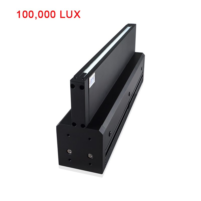
LXV-4LINA uses a 48 mm-wide, 105.5 mm-high housing to project a slender linear field where a conventional illumination head cannot be positioned. The published range covers ten 24 V lengths from 100 to 1000 mm and is intended for display dust, contour-edge, cleanroom and other continuous inspection tasks. Final optical output, controller choice and mounting details must be confirmed for the selected row and workpiece.
- Lengths
- 100–1000 mm
- Ten published rows
- Supply
- 24 V
- Every row
- Power range
- 14.4–168 W
- Model dependent
- Housing section
- 48 × 105.5 mm
- Published envelope
- Output form
- Slender line
- Narrow-space use
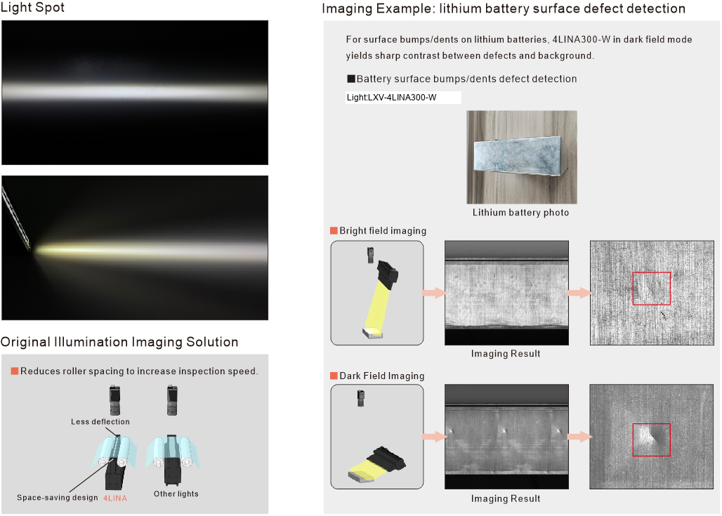
Display dust
Use a narrow illuminated band to reveal contamination on display surfaces.
Restricted installation space
Place the 48 mm-wide head where a broader line-light housing cannot fit.
Contour and edge detection
Aim the slender field to separate the required silhouette or boundary.
Cleanroom inspection
Use the enclosed head in a validated cleanroom-compatible installation and cleaning workflow.
Product-specific engineering facts and the validation work required before release
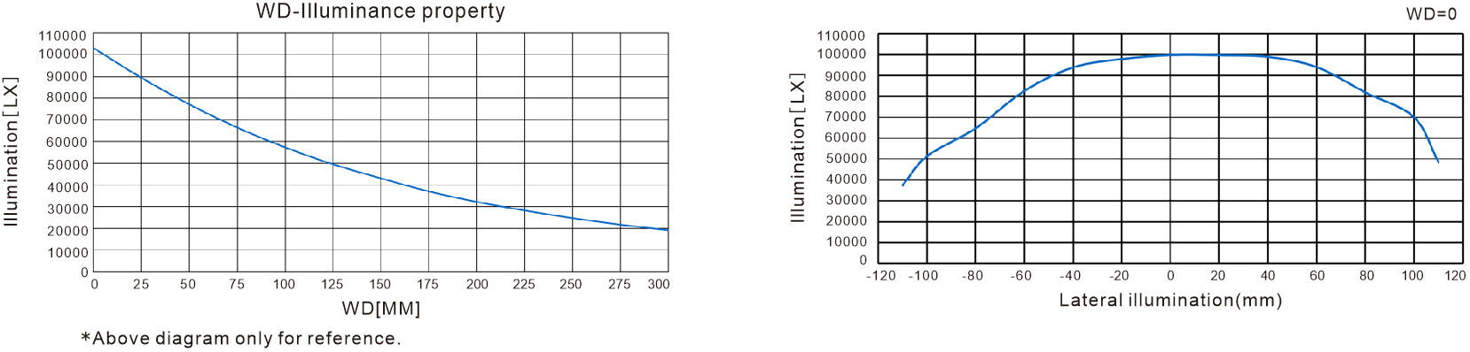
The available product record provides the housing envelope, ten voltage/power rows and stated inspection uses, but no product-specific illuminance curve, field map or mechanical drawing. The page therefore exposes the confirmed values as searchable data and identifies the optical and integration checks that must be measured on the real target.
- Illumination form
- Uniform slender strip
- Narrow-space feature
- 48 mm housing width
- Thermal design
- Large base heat-dissipation area
- Length range
- 100–1000 mm
- Power range
- 14.4–168 W
- Optical curve
- Confirm for selected model
- Field uniformity
- Validate on the real target
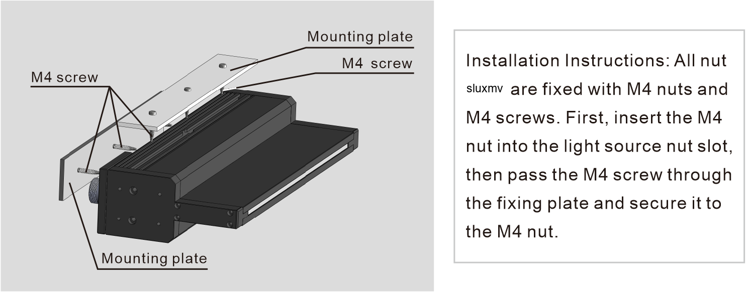
- Mounting drawing
- Confirm before final assembly
Select length and electrical load without transferring values between rows
Every model uses 24 V, but length, total envelope and power change together. Use the complete ten-row table and confirm optical performance and controller headroom for the exact row.
- 1
Define the illuminated line
Measure the required inspection width and add alignment allowance.
- 2
Choose the exact model row
Select 100–1000 mm without interpolating a power value between rows.
- 3
Confirm colour and camera response
Test the selected R, B, G or W option with the actual sensor, lens and surface.
- 4
Size the controller and thermal path
Provide the listed 24 V load plus suitable capacity and heat-dissipation clearance.
Read the source model pattern
LXV-4LINA##-R/B/G/W- LXV-
- Product prefix
- 4LINA
- Narrow line-scan light
- ##
- Nominal emitting-length class
- R/B/G/W
- Colour code
LXV-4LINA model range
Values remain bound to their own model row; colour references are rendered as readable codes.
| Model | Colour | Envelope | Voltage | Power |
|---|---|---|---|---|
| LXV-4LINA100-R/BGW | R / B / G / W | L140 × W48 × H105.5 mm | 24 V | 14.4 W |
| LXV-4LINA200-R/BGW | R / B / G / W | L240 × W48 × H105.5 mm | 24 V | 33.6 W |
| LXV-4LINA300-R/BGW | R / B / G / W | L340 × W48 × H105.5 mm | 24 V | 52.8 W |
| LXV-4LINA400-R/BGW | R / B / G / W | L440 × W48 × H105.5 mm | 24 V | 67.2 W |
| LXV-4LINA500-R/BGW | R / B / G / W | L540 × W48 × H105.5 mm | 24 V | 76.8 W |
| LXV-4LINA600-R/BGW | R / B / G / W | L640 × W48 × H105.5 mm | 24 V | 96.0 W |
| LXV-4LINA700-R/BGW | R / B / G / W | L740 × W48 × H105.5 mm | 24 V | 116 W |
| LXV-4LINA800-R/BGW | R / B / G / W | L840 × W48 × H105.5 mm | 24 V | 135 W |
| LXV-4LINA900-R/BGW | R / B / G / W | L940 × W48 × H105.5 mm | 24 V | 144 W |
| LXV-4LINA1000-R/BGW | R / B / G / W | L1040 × W48 × H105.5 mm | 24 V | 168 W |
Use the published envelope, then close the missing mechanical details before assembly
The row-level envelope is complete enough for preliminary layout, while mounting points, connector orientation, cable bend, emitting-aperture position and cooling clearance require final model confirmation.
- 01
Reserve the selected overall length: nominal length plus 40 mm.
- 02
Reserve the 48 × 105.5 mm housing section throughout the installation path.
- 03
Keep the emitting face clear and align its slender field with the camera line.
- 04
Provide the exact 24 V row power with controller headroom.
- 05
Confirm mounting-hole positions, connector orientation, cable length and thermal clearance before machining brackets.
Use the model row as the mechanical source
No standalone boundary drawing is present in this grouped module. Use the selected family’s complete Dimension value and confirm camera, cable and cooling clearances in the final assembly.
Verify the complete inspection system
- Exact product family and selected model row
- Working distance, field length and lighting geometry
- Voltage, power, controller and cooling method
- Mounting, connector, cable and service clearance