Uniform linear illumination for direct-light and backlight inspection
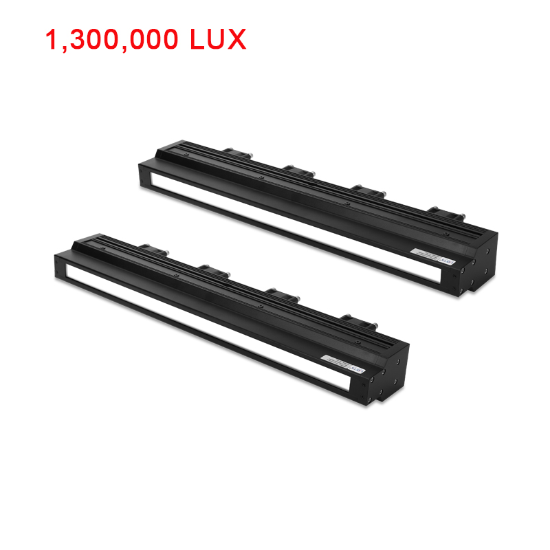
LXV-4LINS is a fan-cooled, high-uniformity line-scan light designed to work with line-scan cameras. Its long emitting surface can be arranged as direct illumination or as a backlight, depending on the contrast mechanism required by the workpiece.
- Listed illuminance
- 1,300,000 lx
- Series value
- Emitting lengths
- 100-1000 mm
- Ten standard white models
- Supply
- 24 V
- 35-324 W by model
- Cooling
- Fan cooling
- Keep fan airflow clear
- Illumination modes
- Direct / backlight
- Choose by inspection geometry
Printing and packaging
Use the uniform linear field to inspect print, registration and packaging surfaces across a moving web.
Plastic-part defects
Apply direct or back illumination according to whether the inspection depends on surface contrast or silhouette.
Ceramic-tile patterns
Use the long, even emitting surface to keep pattern and surface response stable across the camera line.
Metal-surface defects
Evaluate direct illumination where scratches, marks or other surface defects must remain visible across the scan width.
Choose the lighting geometry before choosing the length
Use direct illumination when surface response provides the defect contrast. Use backlighting when the camera needs a silhouette, edge or transmission-based result. Then match the emitting length to the camera line and inspected width.
Output behaviour, illumination modes and optical options
The curves and diagrams below are separated into complete visual modules. Their surrounding labels and engineering meaning are presented as readable webpage content rather than embedded PDF-page text.
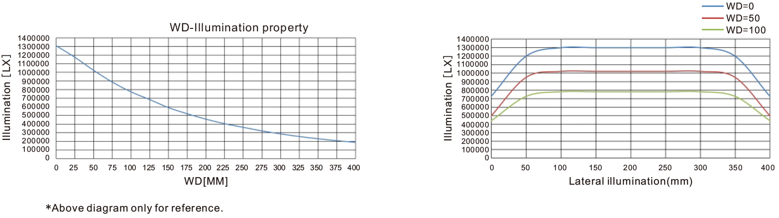
Working distance changes illuminance; the lateral curves show field uniformity
The plots use LXV-4LINS400-W. The working-distance chart records the decrease in illuminance as distance increases. The lateral chart compares the line profile at WD 0, 50 and 100 mm.
Series comparison focuses on output, weight and power
For the comparison shown for the two series, 4LINS is listed with higher luminous output while reducing housing weight and power demand. Confirm final performance with the selected model and actual working distance.
- Brightness comparison
- +30%
- Luminous output improvement in the stated series comparison
- Weight comparison
- -40%
- Weight reduction in the stated series comparison
- Power comparison
- -30%
- Power reduction in the stated series comparison
Use flank lighting for surface contrast or backlighting for transmitted contrast
The same series can be positioned above the target at an angle or beneath a moving web. Keep the camera, target and emitting surface aligned across the full scan width.


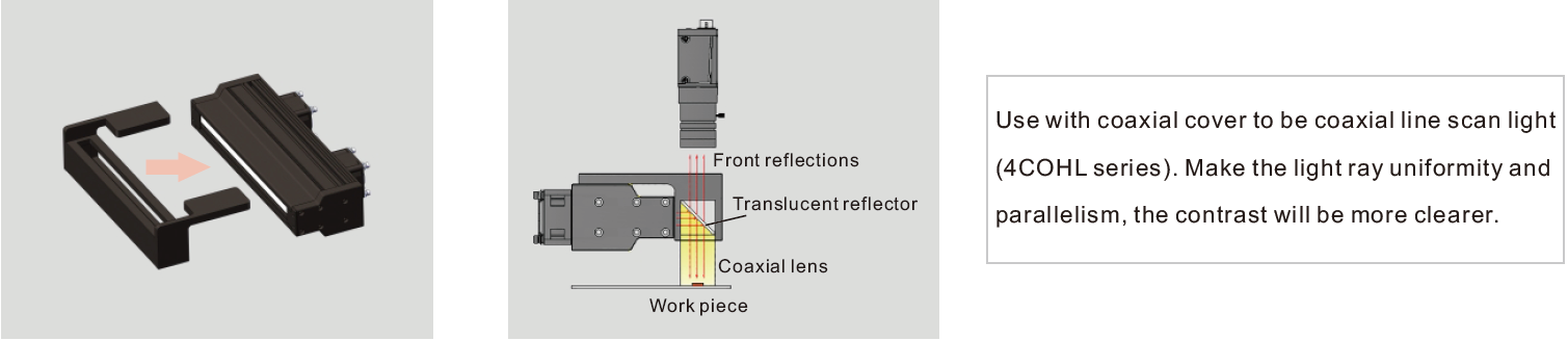
Add the coaxial cover when front-reflected illumination is required
An optional coaxial cover converts the light into the 4COHL-series coaxial line-scan configuration. A translucent reflector redirects the light along the camera axis to improve ray uniformity and parallelism for reflective targets.
Treat this as a different optical arrangement: confirm working distance, reflector clearance and the required contrast on the real surface before final selection.


Select emitting length, colour and controller as one configuration
All standard white models use 24 V and fan cooling. Power, weight, overall length and controller type change by model, so preserve each complete specification row.
- 1
Choose the contrast mechanism
Confirm direct light, backlight or the optional coaxial configuration with the real target.
- 2
Match the emitting length
Choose a 100-1000 mm emitting surface that covers the camera line and inspection width.
- 3
Select colour
Standard color references are red, green, blue and white; UV and IR may be customized.
- 4
Match power and controller
The source table lists a high-power constant-voltage controller and a high-power constant-current controller as the adapted controller options for the series. Confirm the required control mode for the selected light with the complete system.
Read the configuration from the model code
LXV-4LINS##-W- LXV-
- Product prefix
- 4LINS
- High-uniformity line-scan light
- ##
- Emitting-surface length
- W
- White colour code
Electrical and mechanical values by model
All rows list 24 V, white light, 1,300,000 lx, fan cooling, dimension drawing 1 and common signal Y.
| Model | Power | Weight | A: overall | B: emitting |
|---|---|---|---|---|
| LXV-4LINS100 | 35 W | 662 g | 140 mm | 100 mm |
| LXV-4LINS200 | 65 W | 1071 g | 240 mm | 200 mm |
| LXV-4LINS300 | 95 W | 1479 g | 340 mm | 300 mm |
| LXV-4LINS400 | 130 W | 1888 g | 440 mm | 400 mm |
| LXV-4LINS500 | 165 W | 2297 g | 540 mm | 500 mm |
| LXV-4LINS600 | 190 W | 2706 g | 640 mm | 600 mm |
| LXV-4LINS700 | 221 W | 3115 g | 740 mm | 700 mm |
| LXV-4LINS800 | 260 W | 3524 g | 840 mm | 800 mm |
| LXV-4LINS900 | 286 W | 3932 g | 940 mm | 900 mm |
| LXV-4LINS1000 | 324 W | 4341 g | 1040 mm | 1000 mm |
Adapted controller: the series table lists a high-power constant-voltage controller and a high-power constant-current controller; match the actual controller to the chosen electrical configuration.
Peak wavelength / colour temperature: red 620-630 nm; green 525-530 nm; blue 465-470 nm; white 6600 K at room temperature.
Environment: 0-40 degrees C; 20-85% humidity without condensation.
Rated life: 50,000 hours to 50% luminance at the factory-default condition.
Customization: UV and IR are available as customized wavelengths; the model table states a maximum customized product length of 5 m.
Source service note: one year of free technical support and sample free-rent service are listed for this series.
Red, green and blue channels can be controlled independently
The configurable example uses a three-colour line-scan light with separate R, G and B connectors. Define the controller channels, timing and cable layout together with the optical test.

Match cable construction to motion
- PVC extension cable: flexible, bend-resistant and heat-resistant for routing inside equipment
- High-flexibility extension cable: harder and more abrasion-resistant for drag-chain production lines
- Confirm connector access, maximum cable length and controller compatibility before release
Plan mounting, fan clearance and the complete housing envelope
The ten lengths share one drawing format. A is the overall housing length and B is the emitting-surface length. Dimensions are in millimetres.
Fix the light through its M4 nut slots
- Insert the M4 nuts into the housing nut slots.
- Align the light with the fixing plate and inspection line.
- Pass the M4 screws through the fixing plate and tighten them into the nuts.
- Keep the fan inlets, connector and cable bend area unobstructed.

Release the design only after these items agree
- Required emitting width and selected B dimension
- Overall A dimension, mounting slots and service access
- 24 V load, model-specific controller and cable type
- Fan airflow, connector clearance and target working distance