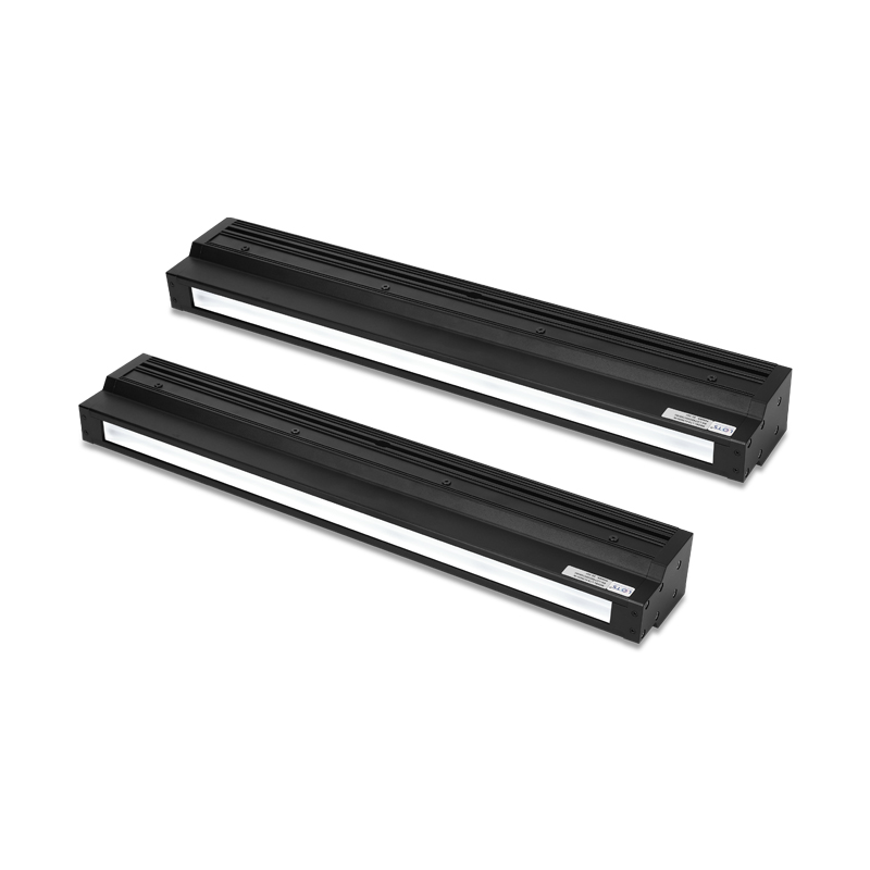
20° oblique line illumination for wrinkle and directional-scratch inspection
LXV-4LIT directs a linear field at a stated 20° angle so a line-scan camera can see relief, wrinkles, loose fibres and scratches that are weak under normal illumination. The available product-specific range contains ten 24 V lengths from 100 to 1000 mm; the light, camera line and material travel direction must be validated together on the real target.
- Illumination angle
- 20°
- Oblique optical design
- Lengths
- 100–1000 mm
- Ten standard rows
- Supply
- 24 V
- Every standard row
- Power range
- 20–168 W
- Model dependent
- Housing section
- 48 × 75 mm
- Published envelope
- Colour options
- R / B / G / W
- UV and IR by request
Textile wrinkles
Aim the oblique line across the moving fabric so height changes create visible contrast.
Carton loose threads
Use the directional field to separate projecting fibres from the carton surface.
Film wrinkles
Orient the 20° light so vertical or directional wrinkles modulate the captured line.
Surface scratches
Rotate the light or workpiece until the scratch direction produces stable contrast across the full scan width.
Product-specific geometry, electrical range and validation boundaries
The verified product record defines the 20° emitting geometry, inspection uses, ten model envelopes and row-level electrical loads. It does not provide a product-specific illuminance curve, uniformity map or mechanical drawing, so those values are treated as measurement and release checks instead of being inferred from another line-light family.
- Optical geometry
- 20° oblique emission
- Inspection mechanism
- Directional contrast for relief and scratches
- Length range
- 100–1000 mm
- Power range
- 20–168 W
- Housing section
- 48 × 75 mm
- Illuminance
- Measure at the selected working distance
- Line uniformity
- Validate across the real field of view
- Mechanical drawing
- Confirm for the selected model before bracket release
Select length, colour and electrical load as one verified configuration
All ten standard rows use 24 V, while overall length and power change with the selected emitting-length class. UV and IR are request options and require wavelength, output and controller confirmation for the application.
- 1
Set the inspection geometry
Define the material travel direction, camera line and defect orientation before choosing the mounting side.
- 2
Choose the exact length row
Cover the full field of view with alignment margin; do not interpolate the load between rows.
- 3
Select colour or wavelength
Test R, B, G or W against the workpiece and camera response; specify UV or IR requirements explicitly.
- 4
Validate contrast and thermal headroom
Confirm the working distance, exposure, uniformity and controller capacity on the selected production-speed sample.
Read the source model pattern
LXV-4LIT##-R/B/G/W- LXV-
- Product prefix
- 4LIT
- 20° oblique line-scan light
- ##
- Nominal emitting-length class
- R/B/G/W
- Colour code
LXV-4LIT model range
Values remain bound to their own model row; colour references are rendered as readable codes.
| Model | Colour | Envelope | Voltage | Power |
|---|---|---|---|---|
| LXV-4LIT100-R/BGW | R / B / G / W | L140 × W48 × H75 mm | 24 V | 20 W |
| LXV-4LIT200-R/BGW | R / B / G / W | L240 × W48 × H75 mm | 24 V | 34 W |
| LXV-4LIT300-R/BGW | R / B / G / W | L340 × W48 × H75 mm | 24 V | 53 W |
| LXV-4LIT400-R/BGW | R / B / G / W | L440 × W48 × H75 mm | 24 V | 68 W |
| LXV-4LIT500-R/BGW | R / B / G / W | L540 × W48 × H75 mm | 24 V | 87 W |
| LXV-4LIT600-R/BGW | R / B / G / W | L640 × W48 × H75 mm | 24 V | 101 W |
| LXV-4LIT700-R/BGW | R / B / G / W | L740 × W48 × H75 mm | 24 V | 116 W |
| LXV-4LIT800-R/BGW | R / B / G / W | L840 × W48 × H75 mm | 24 V | 135 W |
| LXV-4LIT900-R/BGW | R / B / G / W | L940 × W48 × H75 mm | 24 V | 154 W |
| LXV-4LIT1000-R/BGW | R / B / G / W | L1040 × W48 × H75 mm | 24 V | 168 W |
Reserve the complete envelope and preserve the 20° optical path
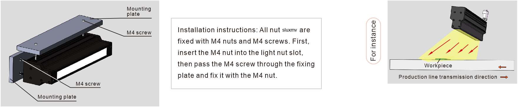
The row table provides the preliminary L × W × H envelope. Mounting points, connector orientation, cable bend, emitting-aperture position and thermal clearances must be confirmed on the exact selected model before machining brackets.
- 01
Reserve the selected overall length: nominal length plus 40 mm.
- 02
Reserve the 48 × 75 mm housing section and an unobstructed 20° emitting path.
- 03
Align the illuminated line with the camera scan line and the defect direction.
- 04
Provide the exact 24 V row load with controller and cable headroom.
- 05
Confirm mounting-hole positions, connector side, cable length and cooling clearance before release.
Use the model row as the mechanical source
No standalone boundary drawing is present in this grouped module. Use the selected family’s complete Dimension value and confirm camera, cable and cooling clearances in the final assembly.
Verify the complete inspection system
- Exact product family and selected model row
- Working distance, field length and lighting geometry
- Voltage, power, controller and cooling method
- Mounting, connector, cable and service clearance