Thin-slit directional illumination for pin location and measurement
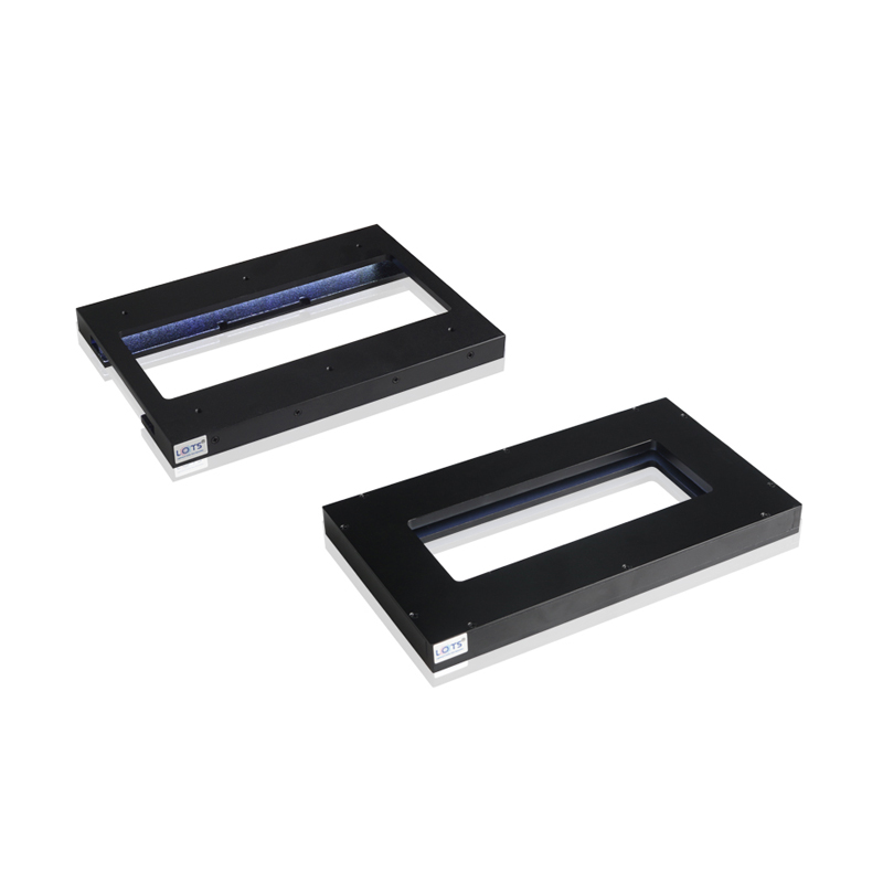
LXV-BRV is a pin inspection light built with surface-mount LEDs. Its thin, strongly directional output highlights raised pins while suppressing background interference; the PDF also identifies matching brightening-strobe control for high-speed applications.
- Standard bodies
- 5
- 120 × 75 to 190 × 110 mm
- Supply
- 24 V
- Every source row
- Power
- 2.9–17.3 W
- Colour and body dependent
- Emitting areas
- 2 or 4
- Encoded by the final suffix
- Documented result
- Distinct without interference
- LXV-BRV150120-W2
Pin location
Highlight the position of raised pins against the background.
Pin measurement
Create clear pin edges for position and dimensional analysis.
Small-item inspection
Inspect slender or elevated features whose background should be suppressed.
High-speed pin inspection
Pair the selected 24 V light with a suitably rated strobe controller and validate timing.
BRV background suppression, configurable body and documented pin result
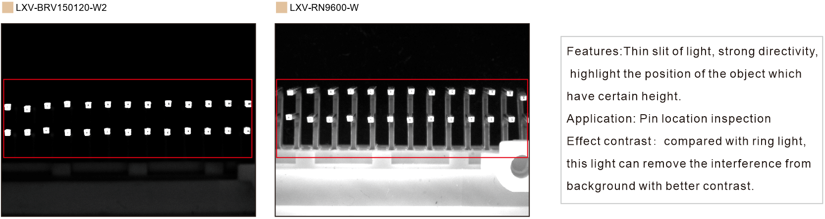
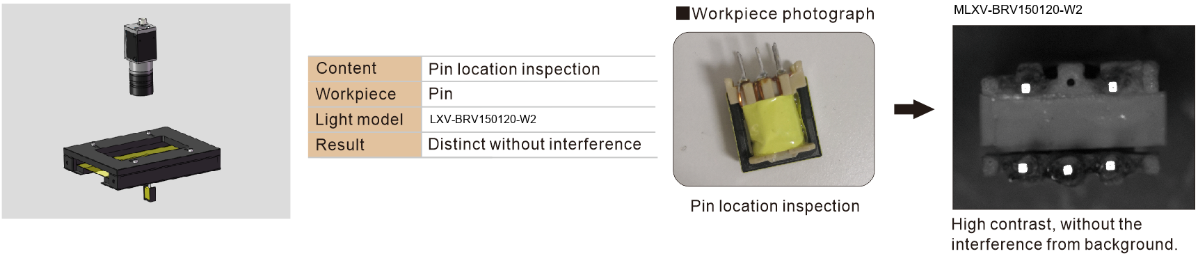
The source directly compares LXV-BRV150120-W2 with ring light LXV-RN9600-W, then documents the camera arrangement, workpiece and high-contrast result for pin-location inspection.
Effect contrast · BRV versus ring light
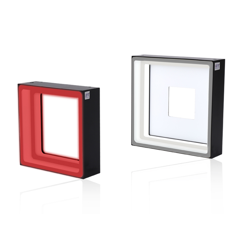
Configurable BRV construction
LXV-BRV150120-W2 pin-location sequence
- Comparison model
- LXV-BRV150120-W2 vs LXV-RN9600-W
- Feature
- Thin slit · strong directivity
- Application
- Pin location inspection
- Result
- Distinct without interference
Select the two- or four-emitting-area body from the exact pin field and load
The five standard bodies have different envelopes, emitting-area counts, colour-dependent powers, mass and mounting drawings. Keep every electrical and mechanical value attached to its own row.
The PDF defines LXV-BRV as a surface-mount-LED pin inspection light with a thin, strongly directional slit of light. The documented comparison uses LXV-BRV150120-W2 against LXV-RN9600-W; the application sequence identifies pin-location inspection, pin workpiece, LXV-BRV150120-W2 and a distinct result without background interference.
- 1
Define pin field and height
Record the pin-array length, width, raised height and direction that must be separated from the background.
- 2
Choose two or four emitting areas
Use the final 2/4 suffix and source drawing together; do not infer the layout from a neighbouring body.
- 3
Choose colour and exact power
Match material response with red, green, blue or 6600 K white and size the controller from that row.
- 4
Validate the captured result
Confirm exposure, strobe timing and background suppression with the production workpiece.
Read the product model pattern
LXV-BRV ## ## - R/G/B/W/IR/UV 2/4- LXV
- Product prefix
- BRV
- Pin inspection light
- First ##
- Overall length
- Second ##
- Overall width
- R/G/B/W/IR/UV
- Colour or wavelength code
- 2 / 4
- Number of emitting areas
LXV-BRV model and optical selection tables
Each value remains attached to its own model or lens row.
Pin inspection light models
| Model pattern | Voltage | Power · R | Power · G/B/W | Weight | Controller | Drawing | Common |
|---|---|---|---|---|---|---|---|
| LXV-BRV12075-[R/G/B/W]2 | 24 V | 2.9 W | 5.8 W | 261 g | Analog / digital / strobe | 1 | Y |
| LXV-BRV120110-[R/G/B/W]4 | 24 V | 11.6 W | 11.6 W | 383 g | Analog / digital / strobe | 2 | Y |
| LXV-BRV150120-[R/G/B/W]2 | 24 V | 8.7 W | 11.6 W | 441 g | Analog / digital / strobe | 3 | N |
| LXV-BRV170120-[R/G/B/W]2 | 24 V | 8.7 W | 11.6 W | 500 g | Analog / digital / strobe | 4 | Y |
| LXV-BRV190110-[R/G/B/W]4 | 24 V | 14.4 W | 17.3 W | 513 g | Analog / digital / strobe | 5 | N |
Spectrum, environment and service references
| Item | PDF value |
|---|---|
| Red | 620–630 nm |
| Green | 525–530 nm |
| Blue | 465–470 nm |
| White | 6600 K colour temperature |
| Optional wavelengths | UV and IR may be customized |
| Operating temperature | 0–40 °C |
| Operating humidity | 20–85% RH · non-condensing |
| Reference life | 50,000 h at 50% of factory-default luminance |
| Value-added service | One year free technical support · sample free-rent service |
Mechanical envelope and mounting reference
| Drawing · body | Envelope | Opening / inner reference | Mounting reference | Lead |
|---|---|---|---|---|
| 1 · LXV-BRV12075 | 120 × 75 × 13.5 mm | 46 × 35 mm; 50.1 × 45.1 mm references | 2 × 4-M3 depth 6 | Two 500 mm leads |
| 2 · LXV-BRV120110 | 120 × 110 × 16 mm | 36 × 46 mm; 75 × 50 mm references | 4-M4 depth 4 | One 500 mm lead |
| 3 · LXV-BRV150120 | 150 × 120 × 26 mm | 46 mm inner width; 45.1 / 100 / 130 mm references | 8-M3 depth 6 | Two 500 mm leads |
| 4 · LXV-BRV170120 | 170 × 120 × 13.5 mm | 130 × 46 mm; 150 × 50.1 mm references | 6-M3 depth 6 | Two 500 mm leads |
| 5 · LXV-BRV190110 | 190 × 110 × 16 mm | 135 × 40 mm; 155 × 50 mm references | 4-M4 depth 4 | One 500 mm lead |
Configurable construction and cables
| Area | Source-listed choice |
|---|---|
| Body | Length and width |
| Optical output | Colour or colour temperature · emitting area |
| Integration | Installation method |
| PVC extension cable | High flexibility, bending and high-temperature resistance; for use inside equipment |
| High-flex extension cable | Harder and more abrasion-resistant than PVC; for drag-chain production lines |
Align the complete emitting-area layout and reserve every documented mounting and cable clearance
The complete source group preserves all five bodies, apertures, mounting references, 13.5–26 mm heights and 500 mm lead callouts as one technical object.
- 01
Match drawings 1–5 to the exact 12075, 120110, 150120, 170120 or 190110 body.
- 02
Align the two or four emitting areas with the raised pins and keep the camera sight line clear through the centre.
- 03
Reserve the documented M3 or M4 mounting pattern, one or two 500 mm leads and connector bend space.
- 04
Operate at 0–40 °C and 20–85% RH without condensation, then validate strobe duty and pin contrast.
Verify model, optical result and mechanical fit together
- Exact product model and colour
- Working distance and camera field
- Voltage, power and controller
- Mounting, cable and thermal clearance