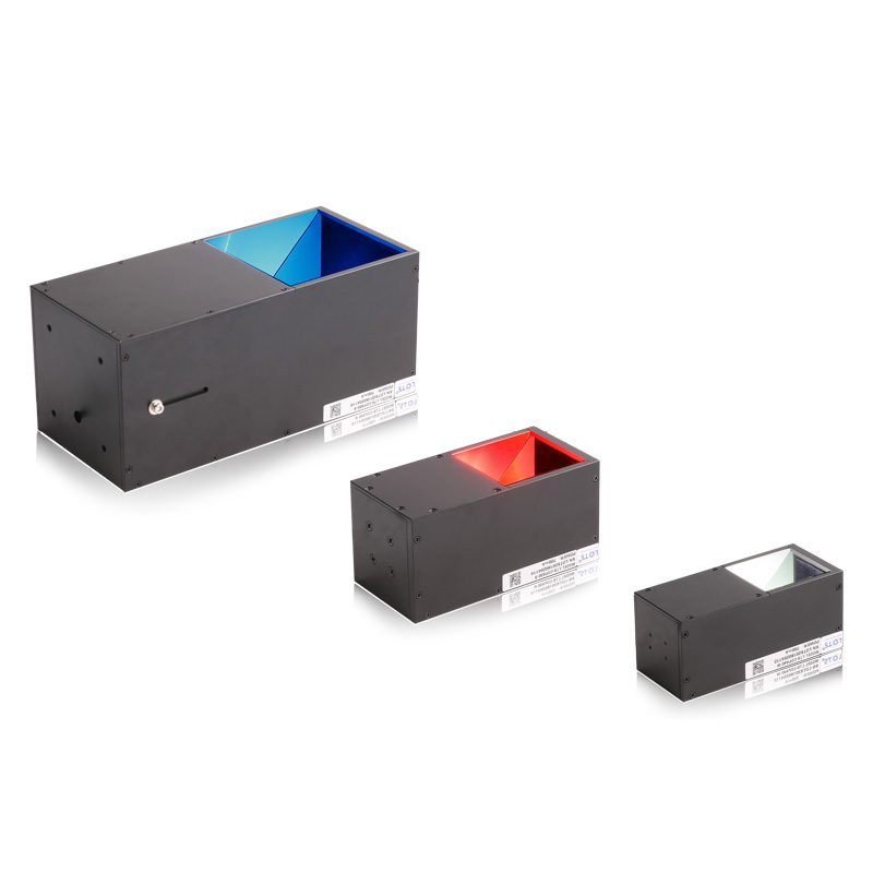
Highly parallel coaxial illumination for reflective surfaces and contamination extraction
LXV-COPA uses a special collimating optical path and a high-power LED to provide bright, uniform and highly parallel coaxial rays. The catalogue documents metal-surface defects, glass, optical-disc scratches, chip scratches and dirty-part inspection, including a glass-plate example in which black contamination is extracted against a whitened background.
- Standard models
- 3
- COPA40 / COPA50 / COPA80
- Catalogue load
- 3 W
- Every colour row shown
- Mass range
- 234–948 g
- Model dependent
- Optical field
- 41 × 55 mm
- COPA50-W maps
- Working-distance plot
- 0–300 mm
- COPA50-W reference
Metal-surface defects
Use the parallel coaxial return to separate small defects from a reflective metal background.
Glass inspection
Inspect reflective glass while preserving a uniform camera-axis field.
Optical-disc scratches
Reveal shallow scratch structure on a highly reflective disc surface.
Chip scratches and dirty parts
Whiten the background and extract dark contamination or scratch features for software recognition.
Measured working-distance response, spot geometry and dirty-part extraction
The catalogue provides an LXV-COPA50-W working-distance curve, relative-irradiance fields at two stated distances, an eight-point light-spot reference, configurable construction choices and a dirty-part inspection instance using LXV-COPA40-B. Numerical and textual content is rebuilt as searchable HTML; the charts, spot geometry and inspection objects remain complete source crops.
LXV-COPA50-W optical reference
Relative illumination is plotted from 0 to 300 mm working distance. The two uniformity maps use the same 41 × 55 mm field of view at LWD 50 mm and LWD 150 mm and share the displayed 10–100 relative-irradiance scale.
Light-spot change with working distance
The source light-spot panel is labelled LXV-COPA50-W. Its complete geometric reference is retained below; the eight diameter and illuminance pairs are transcribed in the measured-reference table.
Dirty-part inspection on a glass plate
The documented instance uses LXV-COPA40-B. The target is a glass plate and the stated result is dirty-part extraction: the background is whitened so black dirty parts remain prominent.
Documented light-spot reference
The source panel label is LXV-COPA50-W; values below are transcribed exactly from that panel.
| Working distance | Spot diameter | Illuminance |
|---|---|---|
| 25 mm | Ø50 mm | 16,350 lx |
| 50 mm | Ø50 mm | 12,720 lx |
| 75 mm | Ø52 mm | 10,600 lx |
| 100 mm | Ø52 mm | 9,330 lx |
| 125 mm | Ø53 mm | 8,460 lx |
| 150 mm | Ø54 mm | 7,740 lx |
| 175 mm | Ø54 mm | 7,114 lx |
| 200 mm | Ø55 mm | 6,435 lx |
- Optical path
- Special collimating design
- Output
- High luminance and uniform rays
- Configurable
- Viewport; body length and width; colour or colour temperature; cable length; installation method
- Application light
- LXV-COPA40-B
Choose the 40, 50 or 80 mm body as one complete catalogue row
The catalogue table contains three standard models only: LXV-COPA40, LXV-COPA50 and LXV-COPA80. Each displayed colour row carries a 3 W entry, while mass and drawing number change by model. Do not infer a COPA100 model or a current value from unrelated product families.
- 1
Define the reflective field
Measure the complete glass, metal, disc or chip area that must receive parallel coaxial light.
- 2
Choose 40, 50 or 80
Match the emitting area and housing envelope to one of the three documented drawings.
- 3
Validate spectral contrast
Test red, green, blue or 6600 K white on the real target; UV and IR may be customised.
- 4
Match the constant-current controller
Use the selected model row and confirm the 3 W catalogue load with the intended controller.
Read the product model pattern
LXV-COPA##-R/G/B/W/IR/UV- LXV
- Product prefix
- COPA
- Collimated coaxial light
- ##
- Width of emitting area
- R/G/B/W
- Standard colour code
- IR/UV
- Custom wavelength option
Complete standard-model reference
The source column is headed “Voltage”, but every entry is printed in watts; the 3 W values below are preserved exactly rather than converted or reinterpreted.
| Model | Catalogue electrical entry | Standard colours | Mass | Controller | Drawing | Common |
|---|---|---|---|---|---|---|
| LXV-COPA40 | 3 W | R / G / B / W | 234 g | Constant current controller | 1 | Y |
| LXV-COPA50 | 3 W | R / G / B / W | 432 g | Constant current controller | 2 | Y |
| LXV-COPA80 | 3 W | R / G / B / W | 948 g | Constant current controller | 3 | Y |
Install the exact COPA housing and preserve the collimated camera-axis path
Three independently cropped drawings retain the complete top, mounting-face and cable views without the large unused page area. Mechanical values are also re-expressed as HTML so each emitting surface, body size, mounting callout and lead length remains attached to its own model.
- 01
Use only the COPA40, COPA50 or COPA80 drawing that matches the selected model.
- 02
Centre the camera, viewing aperture and reflective target on the coaxial optical axis.
- 03
Confirm the configured viewport, body size, cable length and installation method before fabrication.
- 04
Reserve the shown 500 mm lead and connector bend while keeping the emitting window unobstructed.
Spectral, environmental and service reference
| Item | Verified value |
|---|---|
| Red peak wavelength | 620–630 nm |
| Green peak wavelength | 525–530 nm |
| Blue peak wavelength | 465–470 nm |
| White colour temperature | 6600 K |
| Custom wavelength | UV and IR available as required |
| Operating environment | 0–40 °C; 20–85% RH, non-condensing |
| Life-span definition | 50,000 h at 50% luminance reduction from factory default |
| Value-added service | One year free technical support; sample free rent |
Extension-cable choices
| Cable | Documented use |
|---|---|
| PVC extension cable | High flexibility, bending resistance and high-temperature resistance; intended inside equipment. |
| High-flexibility extension cable | Harder and more abrasion resistant than PVC; intended for drag-chain production lines. |
Mechanical envelope by model
| Model | Emitting surface | Internal opening | Body face | Overall length | Mounting face | Mounting | Lead |
|---|---|---|---|---|---|---|---|
| LXV-COPA40 | 38 × 43.4 mm | 33 × 33 mm | 46 × 47 mm | 105.5 mm | 12 / 25 × 30 mm references | 4-M3 depth 5 | 500 mm |
| LXV-COPA50 | 50 × 50 mm | 38 × 38 mm | 60 × 60 mm | 121.5 mm | 18 / 20 × 30 mm references | 4-M3 depth 5 | 500 mm |
| LXV-COPA80 | 80 × 80 mm | 70 × 70 mm | 88 × 86 mm | 164 mm | 18 / 50 × 50 mm references | 4-M4 depth 4.5 | 500 mm |
LXV-COPA40 orthographic references
The emitting face, mounting face and side envelope are isolated as complete views. Native values above retain the shared 26.5 mm internal reference and 500 mm lead.
LXV-COPA50 orthographic references
The three complete views correspond only to COPA50. Native values above retain the 31 mm internal reference, 17 mm cable offset and 500 mm lead.
LXV-COPA80 complete mechanical reference
The COPA80 drawing is already a compact, self-contained model module and therefore remains together at its natural aspect ratio.
Product content is transcribed and reorganised from the verified LXV 2025 catalogue spread whose right-hand printed page is 78. Values are model-specific; do not transfer mass, mounting or dimensional values between rows.
Verify optical result, exact model and installation together
- Target, defect and required contrast
- Field, direction and working distance
- Exact voltage or current and controller load
- Mounting, cable and thermal clearance