Uniform multi-direction shadowless illumination for sloped surfaces, characters and metal edges
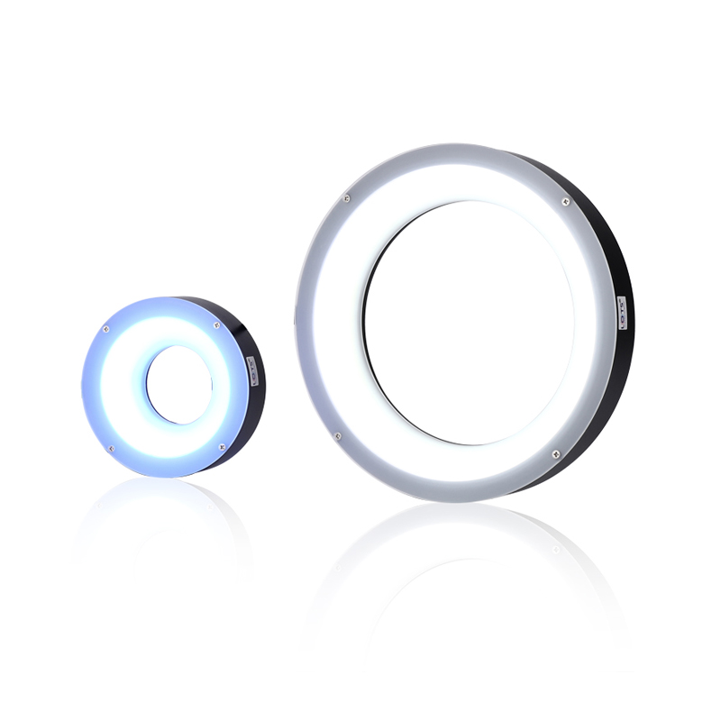
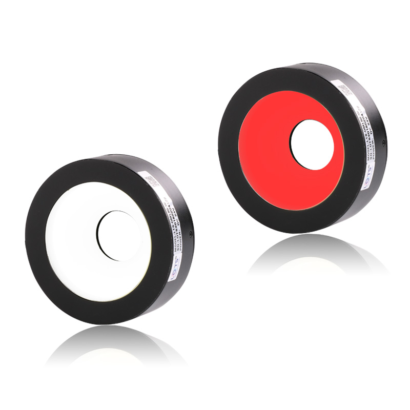
LXV-DML mounts LEDs vertically around the light body and reflects their output through a special diffuser. The resulting ring illumination provides uniform multi-directional light across sloped surfaces for character, pattern, edge-location and measurement inspection.
- Standard models
- 3
- 70 / 90 / 120 mm outer diameter
- Supply
- 24 V
- Every documented row
- Power
- 2.9–7.2 W
- Model and colour dependent
- Optical reference
- LXV-DML90-W
- WD curve + three FOV maps
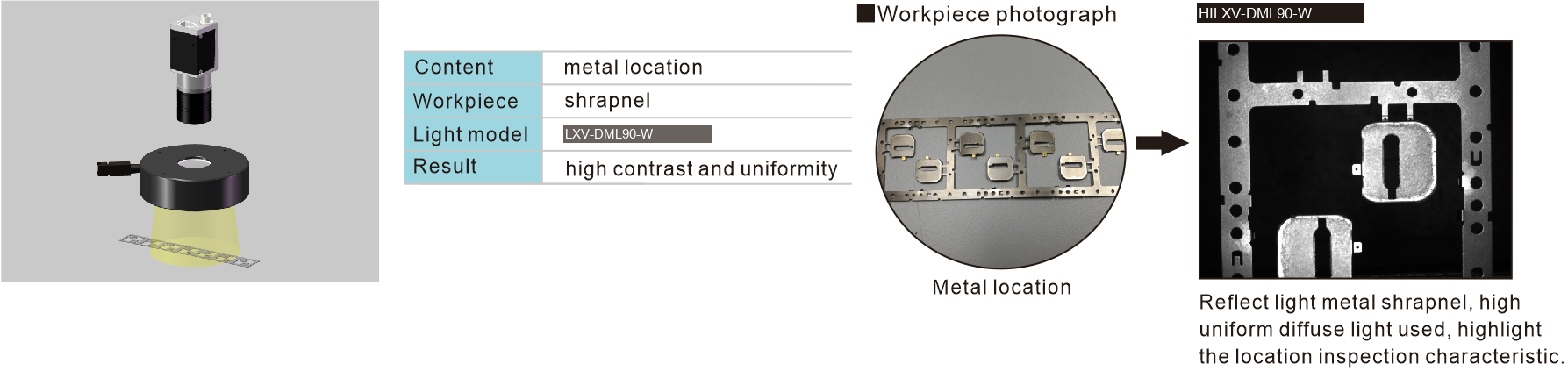
- Application result
- High contrast and uniformity
- Metal shrapnel location
Surface-character recognition
Use uniform reflected illumination to reveal characters on sloped or curved surfaces.
Pattern recognition
Maintain feature visibility across directions instead of relying on a single incident angle.
Metal-object edge location
Highlight the boundary of reflective metal parts with diffuse multi-direction output.
Measurement inspection
Use the stable edge result as input for position and dimensional measurement.
Working-distance response, three luminance fields and metal-location evidence
The PDF documents the LXV-DML90-W working-distance curve, Dark / Medium / High luminance fields at a 40 × 30 mm field of view, configurable construction and a complete metal-shrapnel location sequence.
LXV-DML90-W optical references
Configurable construction
LXV-DML90-W metal-location sequence
- Optical / application model
- LXV-DML90-W
- Uniformity field
- 40 × 30 mm
- Workpiece
- Metal shrapnel
- Result
- High contrast and uniformity
Match the diffuser diameter, aperture and colour to the complete inspection field
The three 24 V models share the same optical principle but differ in outer diameter, emitting surface, mounting circle, power and weight. Keep every electrical and mechanical value attached to its own row.
The PDF defines LXV-DML as Multi-direction Shadowless Light. LEDs are distributed vertically at the side of the light and reflected through a special diffuser to provide uniform output across multiple slopes. UV and IR, shape, aperture, combined light, colour or colour temperature, multi-area control, cable length and installation method are source-listed configuration options.
- 1
Define the feature and direction range
Record whether the task is character, pattern, edge location or dimensional measurement and identify every slope that must remain visible.
- 2
Fit the aperture and emitting surface
Choose the 70, 90 or 120 mm housing while keeping the camera path clear through the stated central opening.
- 3
Choose colour and row power
Use the exact red or G/B/W wattage and validate the material response; UV and IR are source-listed custom options.
- 4
Validate the production result
Check working distance, luminance level, exposure and edge uniformity with the selected controller.
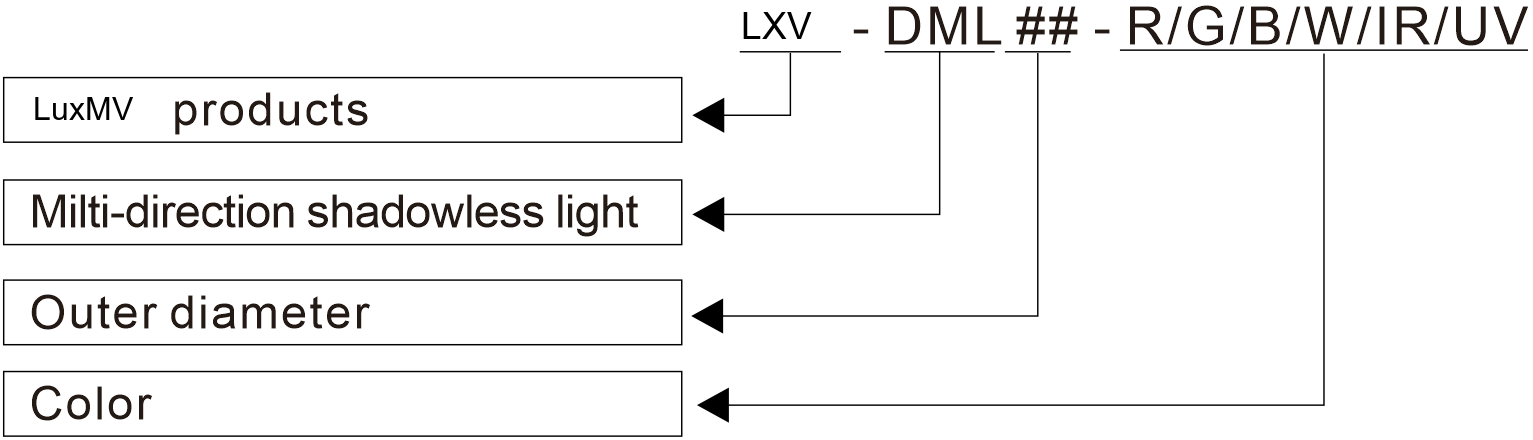
Read the product model pattern
LXV-DML##-R/G/B/W/IR/UV- LXV
- Product prefix
- DML
- Multi-direction shadowless light
- ##
- Outer-diameter code
- R/G/B/W/IR/UV
- Colour or wavelength code
LXV-DML model and optical selection tables
Each value remains attached to its own model or lens row.
Multi-direction shadowless light models
| Model | Voltage | Power · R | Power · G/B/W | Weight | Drawing | Common |
|---|---|---|---|---|---|---|
| LXV-DML70 | 24 V | 2.9 W | 3.6 W | 142 g | 1 | Y |
| LXV-DML90 | 24 V | 4.4 W | 5.8 W | 215 g | 2 | Y |
| LXV-DML120 | 24 V | 5.8 W | 7.2 W | 326 g | 3 | Y |
Colour, wavelength and control
| Item | Source value |
|---|---|
| Red | 620–630 nm |
| Green | 525–530 nm |
| Blue | 465–470 nm |
| White | 6600 K colour temperature |
| Optional wavelengths | UV and IR may be customized |
| Adapted controllers | Strobe controller · analog controller · digital controller |
Native mechanical envelope
| Model | Outer diameter | Central opening | Emitting surface | Height | Mounting reference |
|---|---|---|---|---|---|
| LXV-DML70 | Ø70 mm | Ø28 mm | Ø44 mm | 28 mm | 4 × M3 depth 4 · mounting circle Ø60 |
| LXV-DML90 | Ø90 mm | Ø28 mm | Ø64 mm | 28 mm | 4 × M3 depth 4 · mounting circle Ø76 |
| LXV-DML120 | Ø120 mm | Ø40 mm | Ø94 mm | 28 mm | 4 × M3 depth 4 · mounting circle Ø105 |
Configurable construction
| Item | Source option |
|---|---|
| Housing geometry | Shape · outer and inner diameter |
| Optical configuration | Combined light · multi-area control |
| Spectral configuration | Colour and colour temperature |
| Integration | Cable length · installation method |
Operating, service and cable references
| Item | Source value |
|---|---|
| Operating temperature | 0–40 °C |
| Operating humidity | 20–85% RH · non-condensing |
| Reference life | 50,000 h at 50% of factory-default luminance |
| Value-added service | One year free technical support · sample free-rent service |
| PVC extension cable | Flexible, bending- and high-temperature-resistant; for use inside equipment |
| High-flex extension cable | Harder and more abrasion-resistant than PVC; for drag-chain production lines |
Centre the DML body and preserve the reflected multi-direction optical path
The complete three-model drawing group remains one technical object, while the native dimension table makes every housing, opening, emitting surface and mounting value searchable.
- 01
Match drawing numbers 1–3 to the exact selected model row.
- 02
Centre the camera through the 28 or 40 mm opening and keep the emitting surface unobstructed.
- 03
Reserve the 500 mm lead, connector bend and four M3 mounting locations.
- 04
Operate at 0–40 °C and 20–85% RH without condensation, then verify the final edge result.
Verify model, optical result and mechanical fit together
- Exact product model and colour
- Working distance and camera field
- Voltage, power and controller
- Mounting, cable and thermal clearance