Collimated collector illumination for long-distance character, scratch and edge inspection
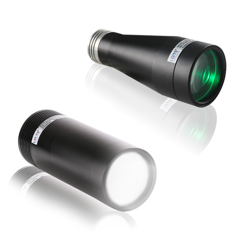
LXV-HSL provides concentrated, high-luminance illumination with good parallelism for long-distance inspection. Its durable, stable housing is designed for heat dissipation, while the verified HSL references cover PCB characters, surface scratches, edge contours, mark positioning and transparent-glass dead-pixel inspection.
- Published models
- 3
- Two housing envelopes
- Drive current
- 1000 / 1500 mA
- Exact model and colour row applies
- Power
- 3 / 5 W
- Exact model and colour row applies
- Reference FOV
- 40 × 55 mm
- LWD 230 and 330 mm
- Longest optical point
- 2000 mm
- 170 mm spot / 912 lx reference
PCB printed characters
Use concentrated illumination to preserve printed-character contrast from a practical stand-off.
Surface scratches
Direct the parallel field across the target to separate scratch contrast.
Edge contours and marks
Create a defined circular field for contour measurement and mark positioning.
Transparent-glass dead pixels
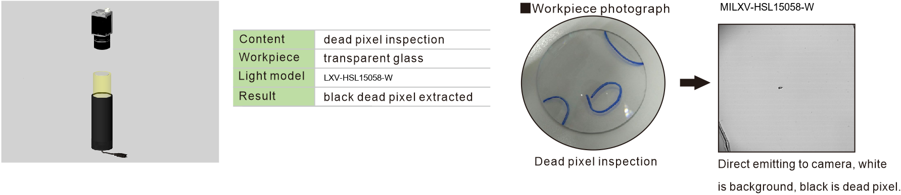
Direct white light toward the camera so the glass appears bright and a dead pixel appears black.
Working-distance behaviour, field uniformity and dead-pixel inspection
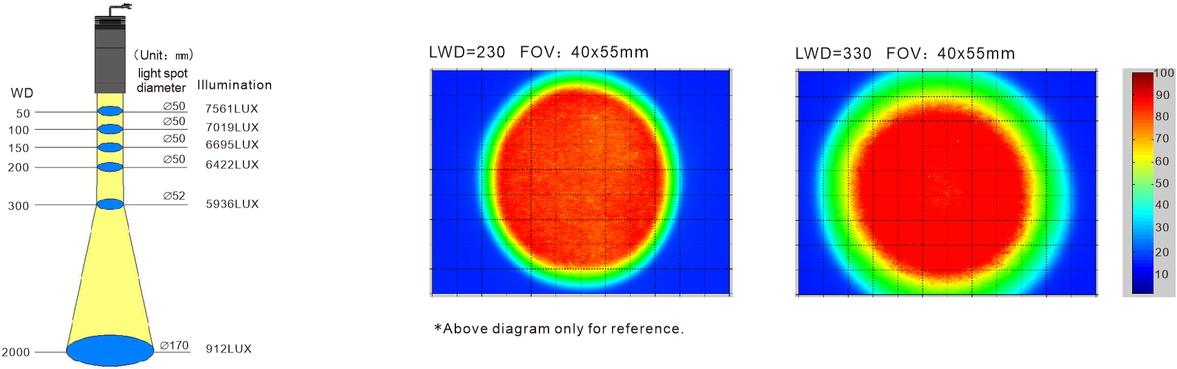
The HSL optical reference keeps a 50 mm spot from 50 to 200 mm working distance, expands to 52 mm at 300 mm and reaches 170 mm at 2000 mm. Two 40 × 55 mm irradiance fields show the distribution at LWD 230 mm and LWD 330 mm. A separate LXV-HSL15058-W example extracts a black dead pixel from transparent glass.
HSL working-distance and irradiance reference
Illuminance decreases from 7,561 lx at 50 mm to 912 lx at 2000 mm. The two relative-irradiance maps use the same 40 × 55 mm field of view and shared 10–100 scale.
LXV-HSL15058-W transparent-glass dead-pixel example
The inspection content is dead-pixel inspection on transparent glass. With direct white emission toward the camera, the background is white and the extracted dead pixel is black.
HSL spot diameter and illuminance reference
| Working distance | Spot diameter | Illuminance |
|---|---|---|
| 50 mm | 50 mm | 7,561 lx |
| 100 mm | 50 mm | 7,091 lx |
| 150 mm | 50 mm | 6,695 lx |
| 200 mm | 50 mm | 6,422 lx |
| 300 mm | 52 mm | 5,936 lx |
| 2000 mm | 170 mm | 912 lx |
- Output
- High luminance and concentrated light
- Parallelism
- Good
- Housing
- Durable, stable and heat dissipating
- Application light
- LXV-HSL15058-W
Choose the housing, colour load and current as one verified row
Three published HSL configurations are available. The 15058 housing has separate 3 W / 1000 mA RBG and 5 W / 1500 mA white rows, so current and power cannot be inferred from the mechanical envelope alone.
- 1
Define the target and field
Record the printed feature, scratch, contour, mark or dead pixel and the camera field of view.
- 2
Validate the working distance
Use the six-point optical reference as a starting point, then test the real target and lens.
- 3
Choose colour and drive row
Keep the selected colour, current and power attached to the exact HSL model row.
- 4
Confirm the controller
Select a controller that supplies the stated current and power; the controller model is not specified in the available HSL data.
Read the product model pattern
LXV-HSL[overall length][outer diameter]-[colour]- LXV
- Product prefix
- HSL
- Collimated collector light
- Overall length
- Housing length in millimetres
- Outer diameter
- Maximum housing diameter in millimetres
- R/B/G/W or RBG
- Published colour configuration
Complete published HSL model reference
| Model | Colour | Mechanical envelope | Drive current | Power |
|---|---|---|---|---|
| LXV-HSL11070-R/BGW | R / B / G / W | L 110 × outer Ø70 mm | 1000 mA | 3 W |
| LXV-HSL15058-RBG | R / B / G | L 150.5 × outer Ø58 mm | 1000 mA | 3 W |
| LXV-HSL15058-W | W | L 150.5 × outer Ø58 mm | 1500 mA | 5 W |
Install from the verified envelope and confirm the project-specific interface
The available HSL data defines overall length and maximum outer diameter but does not provide a verified mounting-hole drawing or cable-exit envelope. Use the dimensions below for initial space allocation, then confirm the mounting interface, connector and service clearance before release.
- 01
Keep the collector and camera aligned with the circular inspection field.
- 02
Reserve at least the listed housing length and outer diameter for the selected model.
- 03
Provide the exact 1000 or 1500 mA drive row and its stated power.
- 04
Confirm mounting, cable exit, connector and thermal clearance on the project drawing.
Verified HSL integration envelope
| Model / configuration | Overall length | Maximum outer diameter | Drive | Power |
|---|---|---|---|---|
| LXV-HSL11070-R/BGW | 110 mm | 70 mm | 1000 mA | 3 W |
| LXV-HSL15058-RBG | 150.5 mm | 58 mm | 1000 mA | 3 W |
| LXV-HSL15058-W | 150.5 mm | 58 mm | 1500 mA | 5 W |
Project details to confirm
| Item | Required confirmation |
|---|---|
| Mounting interface | Hole pattern, thread and orientation |
| Cable and connector | Exit direction, connector type and routing clearance |
| Controller | Current capacity, channel count and operating mode |
| Optical validation | Working distance, field coverage, exposure and target contrast |
HSL selection uses only the HSL-specific model records and technical references shown here. LXV-2HSL voltage, controller, mass and mechanical values do not apply to this family.
Verify optical result, exact model and installation together
- Target, defect and required contrast
- Field, direction and working distance
- Exact voltage or current and controller load
- Mounting, cable and thermal clearance