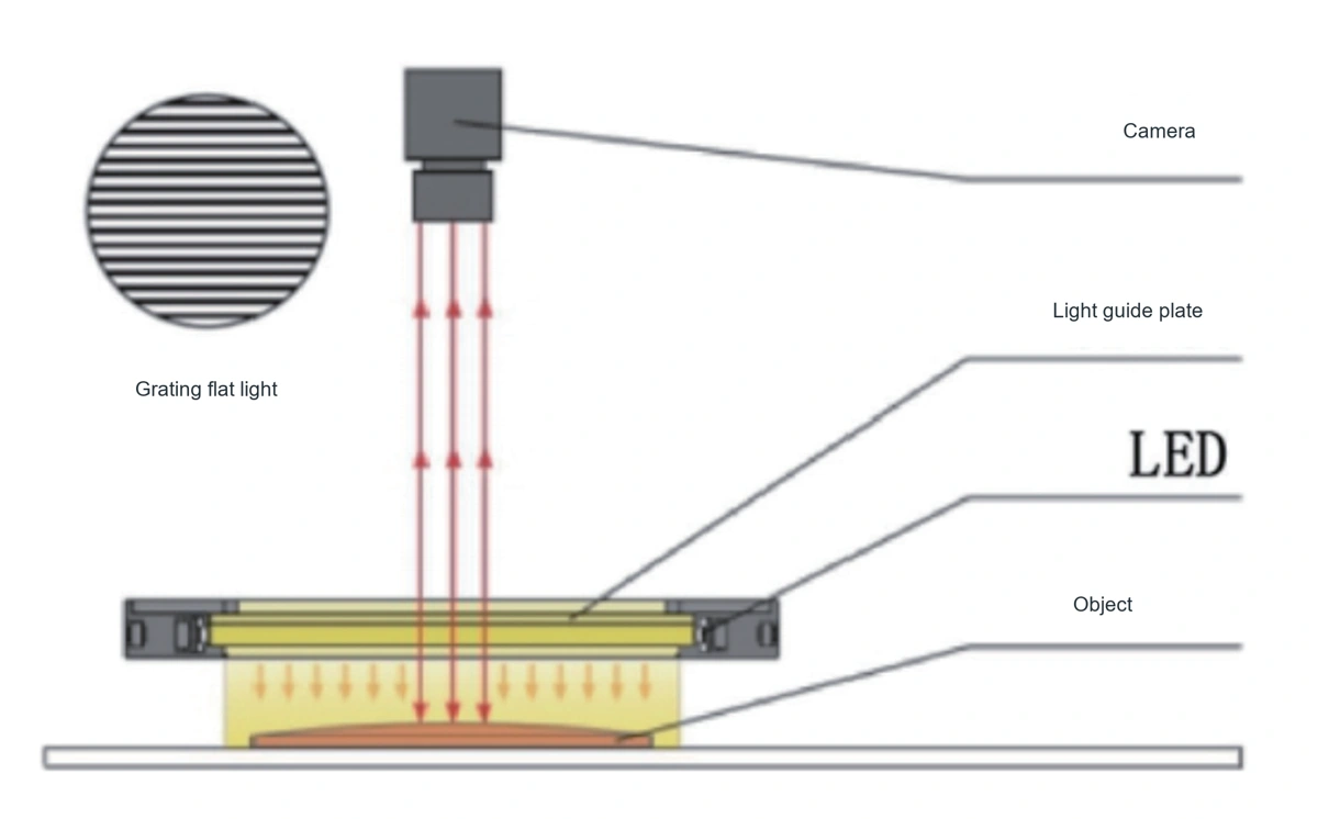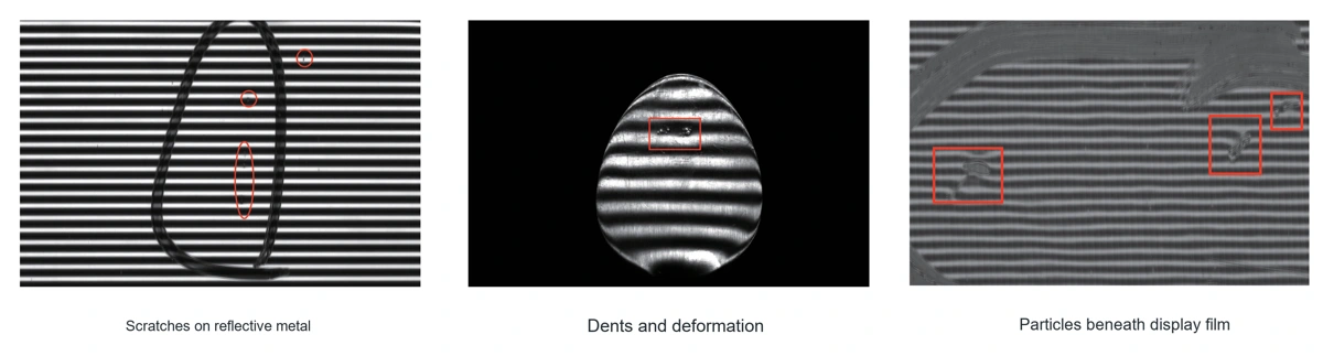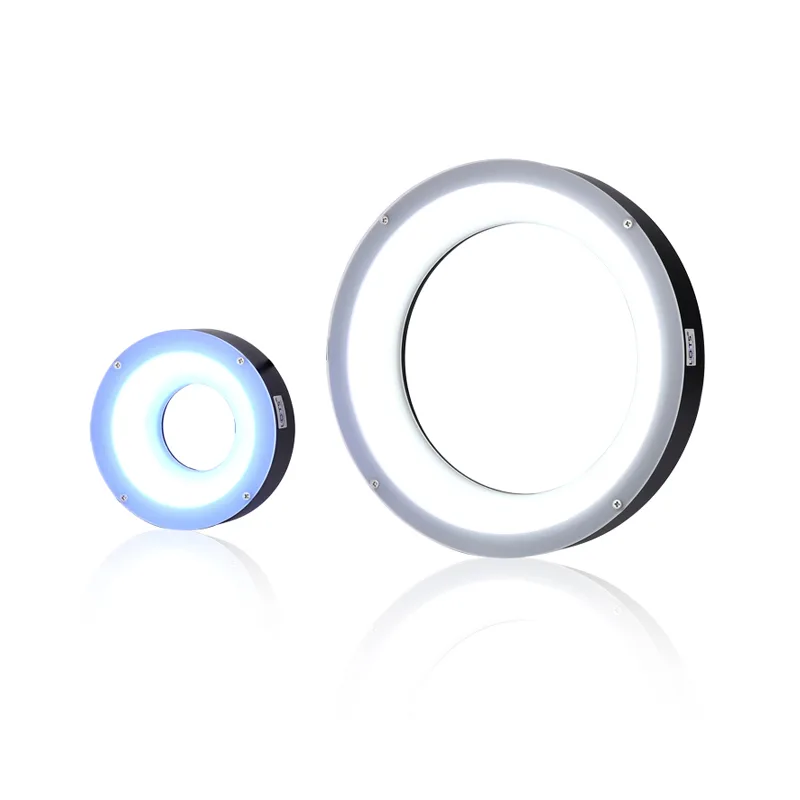
LXV-LF/GS Grating Flat Diffuse Light
LXV-LF/GS is part of the Machine Vision Light range. Confirm the inspection and integration constraints before selecting a configuration.
Target and defect
Define the material, surface, feature or defect and the contrast the image must reveal.
Image geometry
Record field of view, working distance, camera position and the available optical envelope.
Operating conditions
Capture line or cycle speed, exposure, trigger timing, ambient light and environmental limits.
Acceptance criteria
Agree the smallest acceptable feature, repeatability target and sample set used for validation.
Optical behaviour, application examples and product options
Review the optical results, installation views and product options that apply to this model. Every retained visual can be opened at its original resolution.
Match the inspection task to the product characteristics and verify the result on the real target.
Verify the optical result on representative samples
Define the target, imaging geometry and acceptance criteria, then validate contrast and repeatability before fixing the final configuration.
Select the model from the inspection and integration constraints
Compare every applicable row before fixing the configuration.
- 1
Define the inspection target
Record the field of view, smallest feature or defect, material, surface finish and required image contrast.
- 2
Match the operating geometry
Confirm working distance, installation envelope, target motion and the camera or optical interface.
- 3
Compare model-level values
Use the technical table for the selected model; do not apply a value from one row to another model.
- 4
Verify on the real sample
Test the final optical, electrical and timing combination under representative production conditions.
Check mounting, interfaces, clearances and model dimensions
Use only the drawing and specification row that matches the selected model. Allow for connectors, cables, cooling and service access in the machine layout.
Confirm the installation envelope before release
Confirm mounting, connector, cable, cooling and service clearances against the selected configuration before releasing the machine layout.