365–405 nm ultraviolet illumination for high-precision surface, fluorescence and anti-counterfeit inspection
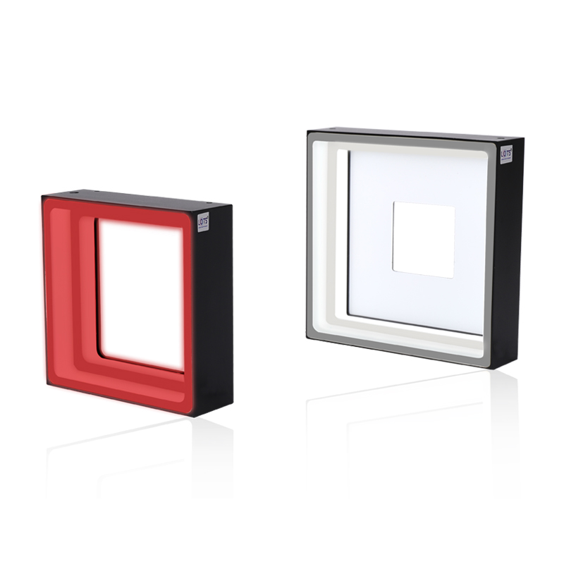
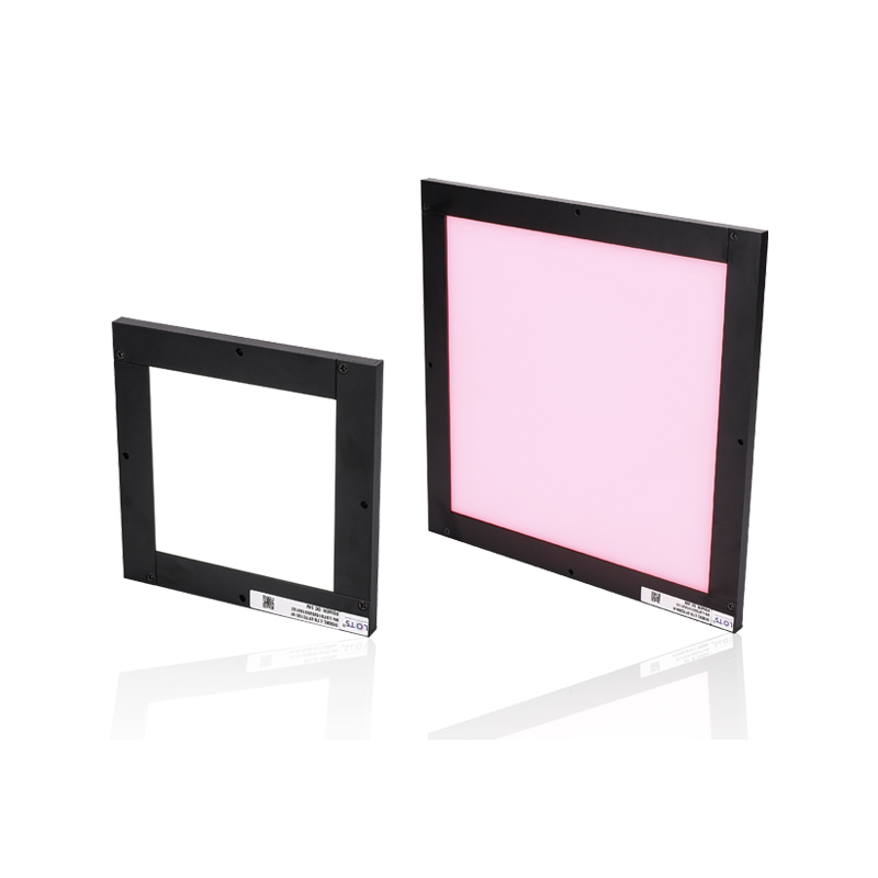
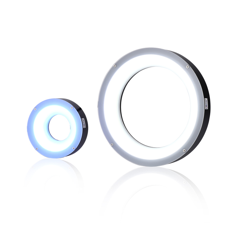
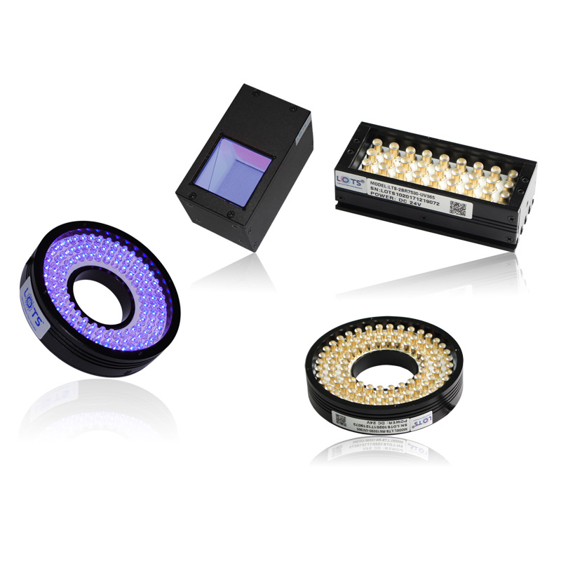
The PDF-defined UV family provides selectable 365–405 nm illumination in ring, coaxial, backlight and bar geometries. It is intended for high-precision work including tiny metal-surface scratches, fluorescent or anti-counterfeit marks, UV-curable printed ink and circuit inspection through plastic film.
- Peak wavelengths
- 365–405 nm
- Selectable UV range
- Forms
- Ring / coaxial / back / bar
- 15 listed models
- Supply
- 24 V
- Every listed row
- Power
- 1.5–19.2 W
- Model dependent
- Controller
- Strobe / analog / digital
- Source-compatible families
Tiny metal-surface scratches
Use a validated UV wavelength and lighting geometry to increase contrast on small surface defects.
Anti-counterfeit inspection
Excite UV-responsive currency, cigarette-case or other security printing.
UV-curable printed ink
Select the wavelength against the documented ink chemistry and process requirement.
Circuit inspection through film
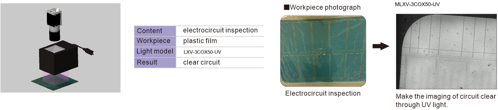
The PDF example uses LXV-3COX50-UV to make circuit structure clear through a plastic-film workpiece.
385/410 nm spectral evidence and a complete circuit-inspection sequence
The PDF separates the UV spectrum, the LXV-RN9030-UV385 working-distance curve and the LXV-3COX50-UV application. They are presented as independent modules so the chart axes, model reference, setup, workpiece and result remain readable.
Ultraviolet spectral and working-distance references
Electrocircuit inspection through plastic film
- Peak range
- 365–405 nm
- Spectrum references
- 385 / 410 nm
- Illumination reference
- LXV-RN9030-UV385
- Application light
- LXV-3COX50-UV
- Workpiece
- Plastic film
- Documented result
- Clear circuit
Choose wavelength and geometry from the target’s UV response
Fifteen source rows cover four illumination forms. Select wavelength, emitting geometry, power and mechanical drawing as one model-specific combination; do not transfer a value between rows.
- 1
Test the target at the candidate wavelength
Select 365–405 nm based on fluorescence, absorption or process response.
- 2
Choose illumination form
Use ring, coaxial, back or bar geometry.
- 3
Match exposure and control
Confirm camera sensitivity and required strobe or continuous mode.
- 4
Apply UV safeguards
Shield unintended exposure and validate materials around the illuminated zone.
Product identity and rows are kept explicit
The PDF states that UV and IR light may be customised as required. It also documents a 0–40 °C non-condensing operating environment, a 50,000 h reference life to 50% factory-default luminance, one year of free technical support, sample free-rent service and two extension-cable constructions. These are published source conditions and options, not guaranteed project outcomes.
Read the product model pattern
LXV-[form][size]-UV- LXV-
- Product prefix
- Form
- RN / 3COX / 4FT / 4BR
- Size
- Geometry-specific code
- UV
- 365–405 nm option
LXV-UV model and parameter range
Every value remains attached to its product-specific row.
Ring and coaxial ultraviolet lights
| Model | Form | Voltage | Power | Peak wavelength | Weight | Controller | Drawing | Common |
|---|---|---|---|---|---|---|---|---|
| LXV-RN5060-UV | Ring | 24 V | 2.0 W | 365–405 nm | 57 g | Strobe / analog / digital | 1 | Y |
| LXV-RN7090-UV | Ring | 24 V | 3.6 W | 365–405 nm | 109 g | Strobe / analog / digital | 2 | Y |
| LXV-RN12030-UV | Ring | 24 V | 7.2 W | 365–405 nm | 222 g | Strobe / analog / digital | 3 | Y |
| LXV-3COX40-UV | Coaxial | 24 V | 1.7 W | 365–405 nm | 186 g | Strobe / analog / digital | 4 | Y |
| LXV-3COX50-UV | Coaxial | 24 V | 3.6 W | 365–405 nm | 308 g | Strobe / analog / digital | 5 | Y |
Back ultraviolet lights
| Model | Voltage | Power | Peak wavelength | Weight | Controller | Drawing | Common |
|---|---|---|---|---|---|---|---|
| LXV-4FT5050-UV | 24 V | 3.6 W | 365–405 nm | 114 g | Strobe / analog / digital | 6 | Y |
| LXV-4FT7070-UV | 24 V | 5.8 W | 365–405 nm | 164 g | Strobe / analog / digital | 7 | Y |
| LXV-4FT8080-UV | 24 V | 7.2 W | 365–405 nm | 186 g | Strobe / analog / digital | 8 | Y |
| LXV-4FT100100-UV | 24 V | 11.6 W | 365–405 nm | 334 g | Strobe / analog / digital | 9 | Y |
| LXV-4FT150150-UV | 24 V | 19.2 W | 365–405 nm | 500 g | Strobe / analog / digital | 10 | Y |
Bar ultraviolet lights
| Model | Voltage | Power | Peak wavelength | Weight | Controller | Drawing | Common |
|---|---|---|---|---|---|---|---|
| LXV-4BR6016-UV | 24 V | 1.5 W | 365–405 nm | 80 g | Strobe / analog / digital | 11 | Y |
| LXV-4BR9016-UV | 24 V | 2.2 W | 365–405 nm | 105 g | Strobe / analog / digital | 11 | Y |
| LXV-4BR18016-UV | 24 V | 5.1 W | 365–405 nm | 181 g | Strobe / analog / digital | 11 | Y |
| LXV-4BR7530-UV | 24 V | 3.6 W | 365–405 nm | 134 g | Strobe / analog / digital | 12 | Y |
| LXV-4BR12530-UV | 24 V | 6.0 W | 365–405 nm | 201 g | Strobe / analog / digital | 13 | Y |
Operating, lifetime, service and customisation references
| Parameter | Published value |
|---|---|
| Operating environment | 0–40 °C; 20–85% RH, non-condensing |
| Reference life | 50,000 h until luminance is reduced to 50% of factory default |
| Value-added service | One year free technical support; sample free-rent service |
| Customisation | UV and IR light may be customised as required |
| Changeable items | Shape; colour / colour temperature; combined light; cable length; multi-area control; installation method; emitting angle |
Extension-cable selection
| Cable | Construction guidance | Recommended placement |
|---|---|---|
| PVC extension cable | High flexibility, bending resistance and high-temperature resistance | Inside equipment |
| High-flexibility extension cable | Harder and more abrasion-resistant than PVC | Drag-chain production-line system |
Mechanical envelope by drawing
| Drawing / models | Overall envelope | Emitting area | Mounting / cable |
|---|---|---|---|
| 1 · LXV-RN5060 | Ø50 × 19.5 mm | Ø28.5 mm opening | 4-M3 depth 5 on Ø42; 500 mm cable |
| 2 · LXV-RN7090 | Ø70 × 20.5 mm | Ø36 mm opening | 4-M3 depth 4.5 on Ø54; 500 mm cable |
| 3 · LXV-RN12030 | Ø120 × 23 mm | Ø80 mm opening | 4-M3 depth 4 on Ø106; 500 mm cable |
| 4 · LXV-3COX40 | 74 × 50 mm housing | 40 × 40 mm | 4-M3 depth 4.5; 30 × 25 pitch; 500 mm cable |
| 5 · LXV-3COX50 | 84 × 60 mm housing | 50 × 50 mm | 4-M3 depth 4.5; 30 × 25 pitch; 500 mm cable |
| 6 · LXV-4FT5050 | 64 × 64 × 17 mm | 50 × 50 mm | 6-M3 depth 4 reverse; 500 mm cable |
| 7 · LXV-4FT7070 | 84 × 84 × 17 mm | 70 × 70 mm | 6-M3 depth 4 reverse; 500 mm cable |
| 8 · LXV-4FT8080 | 94 × 94 × 17 mm | 80 × 80 mm | 6-M3 depth 4 reverse; 500 mm cable |
| 9 · LXV-4FT100100 | 114 × 114 × 17 mm | 100 × 100 mm | 8-M3 depth 4 reverse; 500 mm cable |
| 10 · LXV-4FT150150 | 164 × 164 × 17 mm | 150 × 150 mm | 8-M3 depth 4 reverse; 500 mm cable |
| 11 · LXV-4BR6016 / 9016 / 18016 | A 72 / 102 / 192 mm; 26 × 22 mm section | B 60 / 90 / 180 × 16 mm | 2×2-M3 depth 5; 500 mm cable |
| 12 · LXV-4BR7530 | 87 × 36 × 26 mm | 75 × 30 mm | 2×2-M3 depth 5; 500 mm cable |
| 13 · LXV-4BR12530 | 137 × 36 × 26 mm | 125 × 30 mm | 2×4-M3 depth 5; 500 mm cable |
Use the complete two-part drawing set and protect the UV optical zone
Ring, coaxial, backlight and bar models have different emitting surfaces, mounting patterns and cable envelopes. The native mechanical table and both complete drawing groups must be read together; no dimension is transferred between housings.
- 01
Select the exact UV wavelength, product form, model row and drawing number.
- 02
Align the complete emitting surface with the workpiece and camera field while reserving the documented working distance.
- 03
Match the source-compatible strobe, analog or digital controller and verify total connected power.
- 04
Use the PVC cable inside equipment or the abrasion-resistant high-flex cable in a drag chain as documented.
- 05
Reserve the 500 mm light-cable path, connector bend envelope and service access before release.
- 06
Add project-appropriate UV shielding, access control and exposure validation around the illuminated zone.
Verify the complete imaging system
- Exact wavelength, product form and model row
- Camera and lens spectral response
- Working distance, fibre or emitting geometry
- Controller, trigger, mounting and cable clearance