What inspection variables should be evaluated?
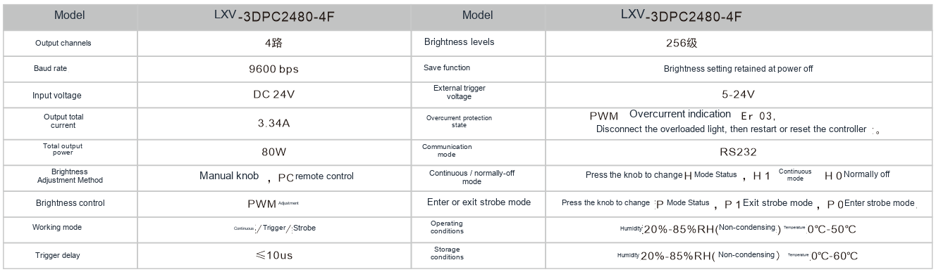
Save channel values and trigger mode for each station. Verify that identical settings are reproduced after restarting.
What lighting geometry fits this inspection task?
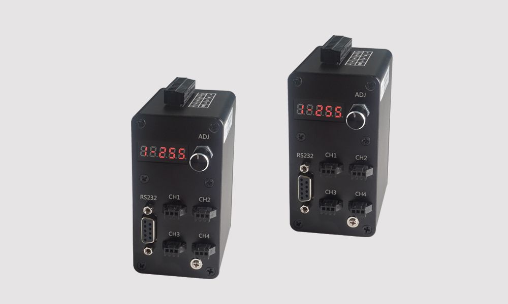
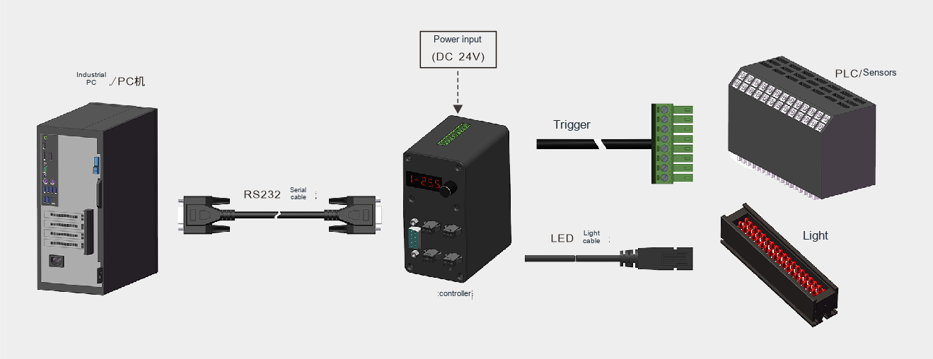
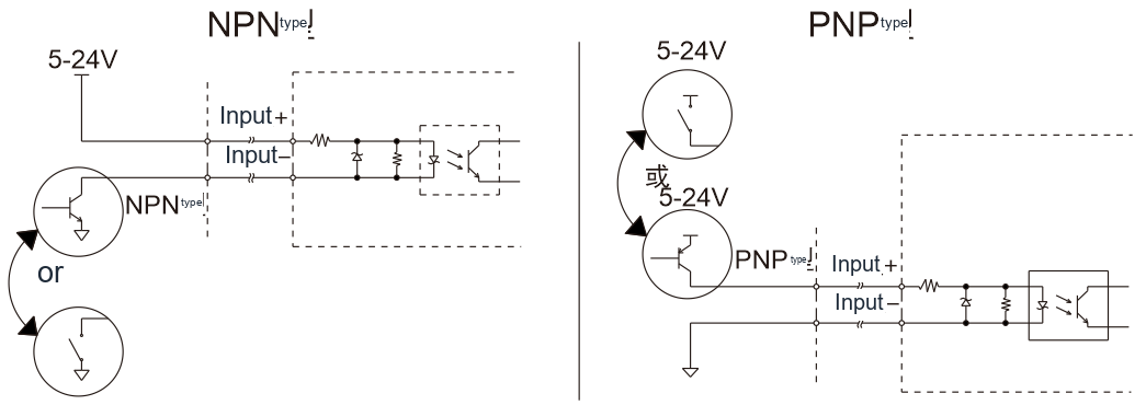
Match the controller to light voltage, current, channels and trigger mode. A similar connector does not make constant-voltage and constant-current devices interchangeable. Check combined channel load, cables and connectors. Protection ratings depend on the exact model.
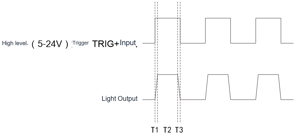
Verify wiring at low output, then test dimming and repeated triggers. For strobing, check pulse width, duty cycle, delay and the light rating together. Save the operating settings and confirm power-recovery behaviour for repeatable production and maintenance.
Related product family?
LXV-3DPC-F
Adjust brightness and coordinate lighting with your camera.
Before choosing a configuration?
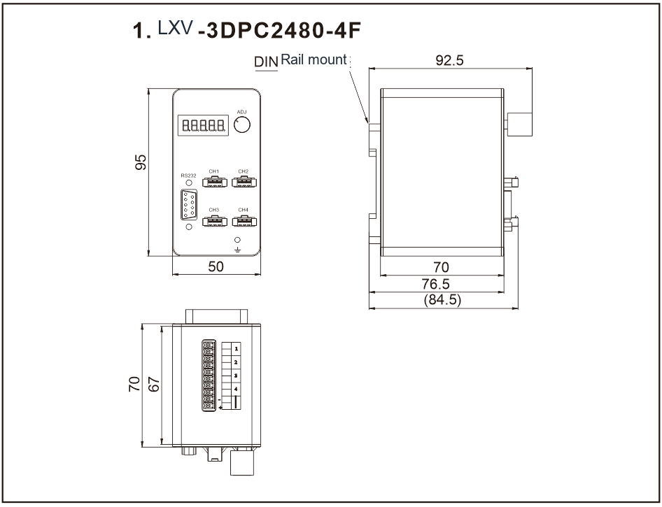
For selection, specify the field of view, smallest target feature, height variation, cycle time and installation space. Use the specific product page and drawing to verify electrical ratings, dimensions and compatibility.
Testing digital brightness recipes?
Match the controller's output type and ratings to the selected light. Define a repeatable recipe containing channel settings, trigger mode and camera exposure. A numeric setting is meaningful only for that complete configuration.
Verify setting recall, communication errors and power-up behaviour. Measure image response over the useful control range rather than assuming equal numeric steps produce equal optical steps. Test the trigger sequence at production speed.
What do the optical setup and sample images show?