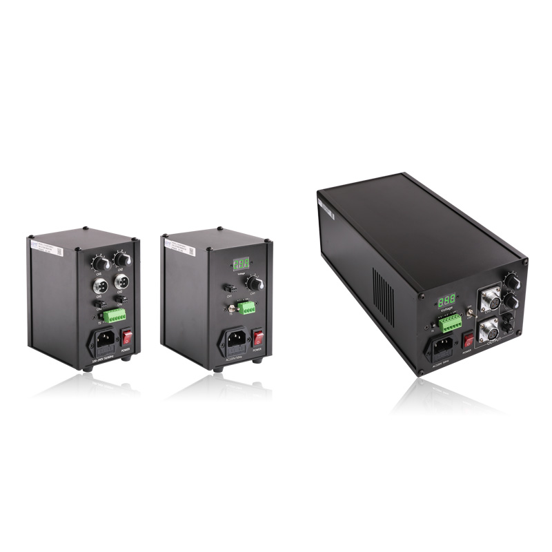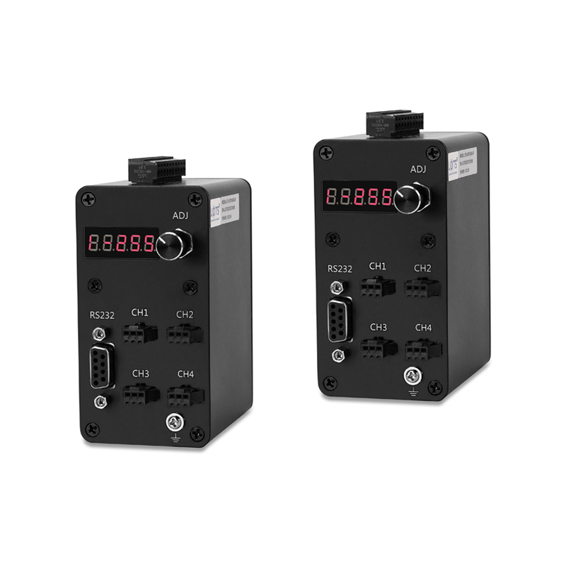
Digital light control for externally triggered, multi-channel machine-vision systems
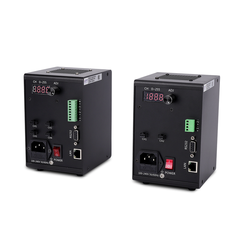
The 3DPC family covers a compact 24 V DC controller box and AC-input digital controllers with RS232 or RS232/LAN communication. Select the exact model from its channel count, load, interface and housing group rather than transferring values between variants.
- Light output
- 24 V
- All listed 3DPC models
- Channel options
- 2–12
- Model-dependent
- Trigger level
- 5–24 V
- External high-level input
- Trigger delay
- 10 μs
- Stated digital-controller value
- Adjustment
- 256 levels
- Manual or PC remote
PLC or sensor triggering
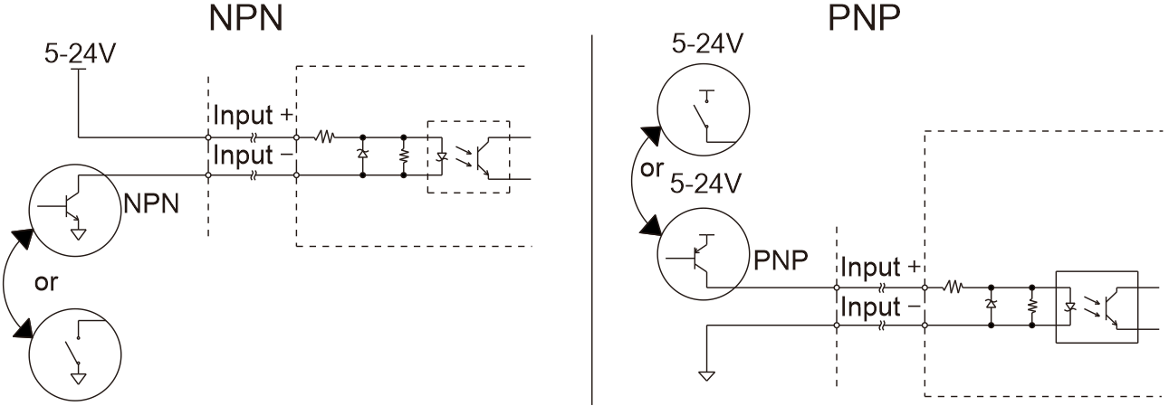
Connect a 5–24 V external trigger through the defined NPN or PNP input circuit.
Multi-light coordination
Choose 2, 4, 8 or 12 output channels to match the number of independently controlled lights.
Local or remote adjustment
Set luminance through the encoder knob or use the supported PC communication interface.
Constant or trigger operation
Use H1/H0 state control and the external-trigger timing relationship shown in the technical evidence.
Confirm the communication group before choosing a channel count
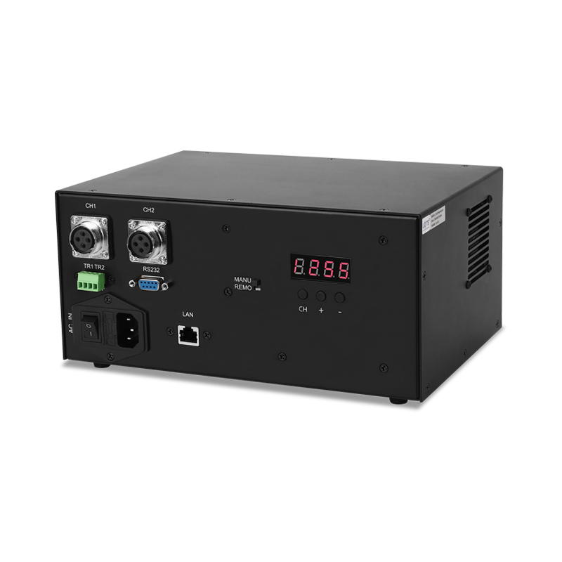
RS232-only models use a C suffix in the listed model rows. RS232/LAN models use an S suffix and include the stated 12 V / 500 mA auxiliary output. The compact LXV-3DPC2480-4F is a separate four-channel, 80 W, DC-input configuration.
System topology, operating parameters and trigger behaviour
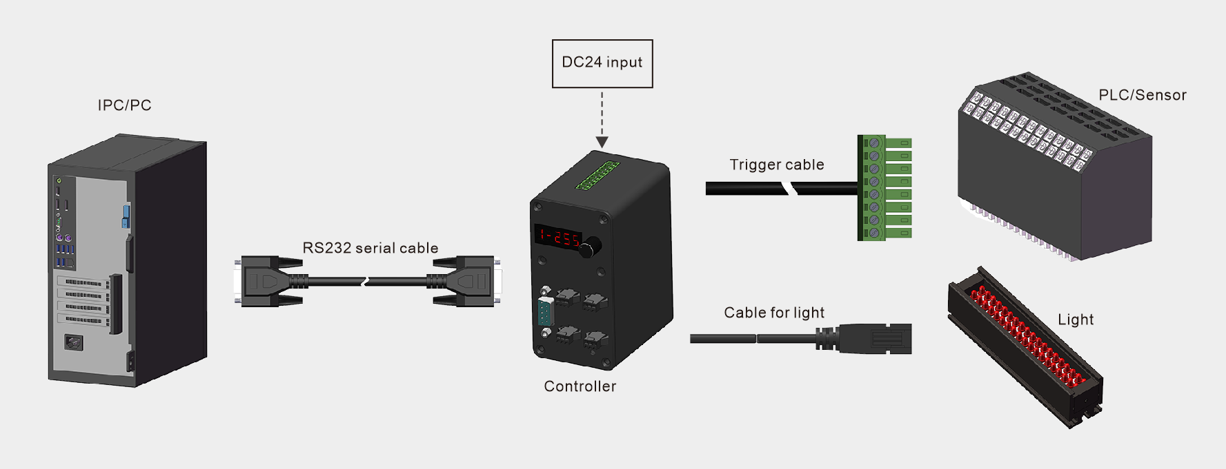
Read the topology and trigger circuit together: the controller sits between PC communication, the PLC or sensor trigger, and the connected light channels.
| Function | Operating parameter |
|---|---|
| Number of channels | 2, 4, 8 or 12, depending on model |
| Communication | RS232, or RS232 / LAN depending on model group |
| Additional output | 12 V / 500 mA on the stated RS232 / LAN group; reverse connection is prohibited |
| Baud rate | Default 19,200 bps |
| Input | 100–240 VAC, 50/60 Hz |
| Light output | 24 V |
| Adjustment | Manual encoder-knob adjustment or PC remote adjustment |
| Drive mode | PWM adjustment |
| Adjustment resolution | 256 levels |
| Memory | Power-off data saving is enabled by default and can be set not to save |
| H mode | H1 constant-on mode / H0 constant-off mode |
| External trigger | Pulse-width trigger; high level 5–24 V is effective |
| Maximum effective trigger frequency | 4 kHz when the external-trigger duty ratio is 50% |
| External trigger delay | 10 μs |
| Operating environment | 20%–85% RH, frost-free; 0°C–50°C |
| Storage environment | 20%–85% RH, frost-free; 0°C–50°C |
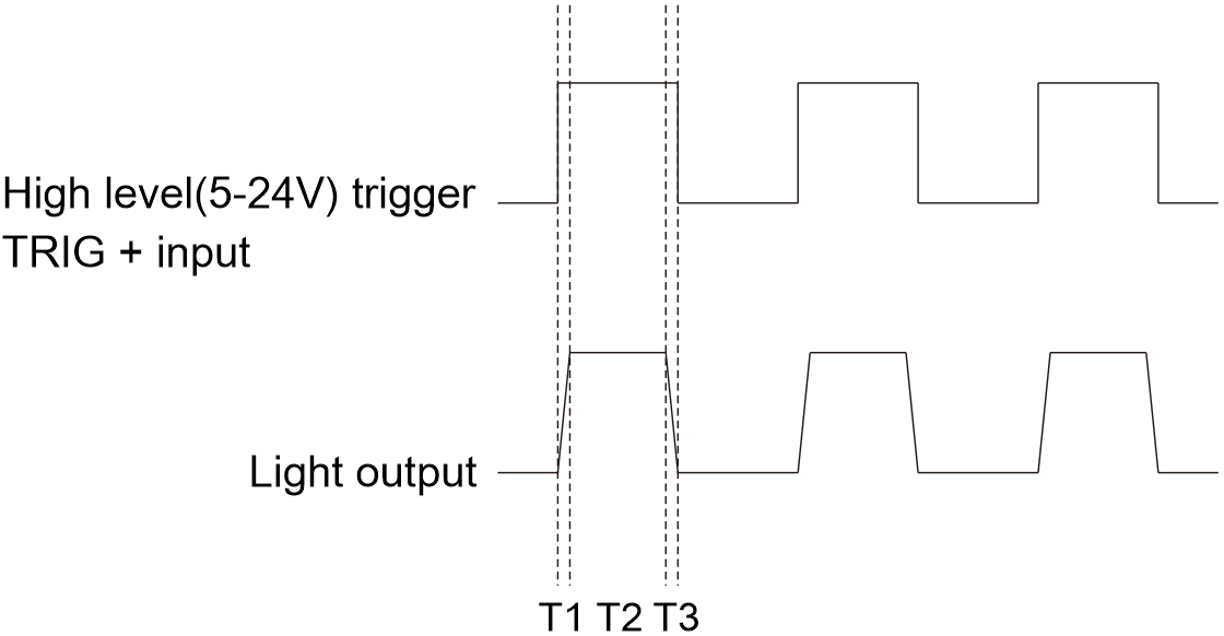
T1 and T3 are the controller response intervals
T1 is the delay before the light turns on, T2 is the lighting time after the trigger, and T3 is the delay before the light turns off. The stated limits are T1 ≤ 10 μs and T3 ≤ 10 μs.
- H1 constant-on mode
- With trigger “+” at 5–24 V and “−” at ground, the light switches off.
- H0 constant-off mode
- With trigger “+” at 5–24 V and “−” at ground, the light switches on.
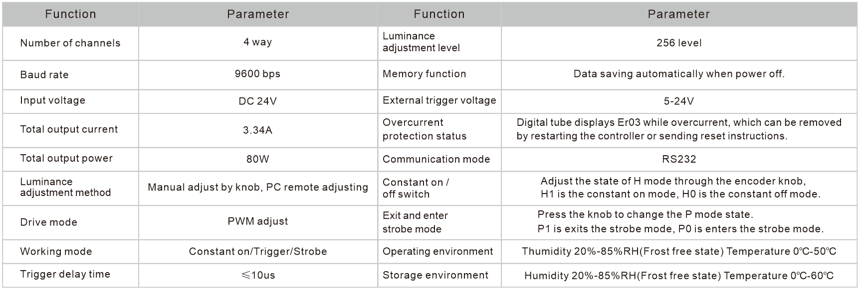
| Channels | 4 | Adjustment | 256 levels |
|---|---|---|---|
| Baud rate | 9,600 bps | Memory | Automatic data saving at power off |
| Input | DC 24 V | External trigger | 5–24 V |
| Total current | 3.34 A | Communication | RS232 |
| Total output | 80 W | Working mode | Constant on / trigger / strobe |
| Drive | PWM adjustment | Trigger delay | ≤ 10 μs |
| Operation | 0°C–50°C, 20%–85% RH | Storage | 0°C–60°C, 20%–85% RH |
Select communication, total load and channel count as one configuration
Every row below is a complete controller configuration. Do not combine the power, channel or dimension value from a different row.
- 1
Choose the controller family
Use the compact DC-input 4F model or the AC-input digital-controller group.
- 2
Choose the interface
Select RS232-only C models or RS232/LAN S models.
- 3
Calculate the connected load
Check both the total output limit and the maximum for one channel.
- 4
Match the housing group
Use dimension group 1, 2 or 3 from the same selected model row.
LXV-3DPC [voltage] [total output power]-[channel / interface suffix]- LXV
- LuxMV product prefix
- 3DPC
- Digital controller
- 24 / 60–200
- 24 V output and model-level total power
- C / S
- Select the RS232 or RS232/LAN model row
| Model | Input | Output | Total | One-channel max. | Channels | Communication |
|---|---|---|---|---|---|---|
| LXV-3DPC2480-4F | DC 24 V | 24 V | 80 W | 80 W | 4 | RS232 |
| Model | Output | Total power | One-channel maximum | Channels | Dimension group | Trigger |
|---|---|---|---|---|---|---|
| LXV-3DPC2460-2C | 24 V | 60 W | 40 W | 2 | 1 | 5–24 V |
| LXV-3DPC2460-4C | 24 V | 60 W | 40 W | 4 | 1 | 5–24 V |
| LXV-3DPC24120-4C | 24 V | 120 W | 60 W | 4 | 1 | 5–24 V |
| LXV-3DPC24200-4C | 24 V | 200 W | 60 W | 4 | 1 | 5–24 V |
| LXV-3DPC24120-8C | 24 V | 120 W | 60 W | 8 | 2 | 5–24 V |
| LXV-3DPC24200-8C | 24 V | 200 W | 60 W | 8 | 2 | 5–24 V |
| Model | Output | Total power | One-channel maximum | Channels | Dimension group | Trigger |
|---|---|---|---|---|---|---|
| LXV-3DPC2460-2S | 24 V | 60 W | 40 W | 2 | 1 | 5–24 V |
| LXV-3DPC2460-4S | 24 V | 60 W | 40 W | 4 | 1 | 5–24 V |
| LXV-3DPC24120-4S | 24 V | 120 W | 60 W | 4 | 1 | 5–24 V |
| LXV-3DPC24200-4S | 24 V | 200 W | 60 W | 4 | 1 | 5–24 V |
| LXV-3DPC24120-8S | 24 V | 120 W | 60 W | 8 | 2 | 5–24 V |
| LXV-3DPC24200-8S | 24 V | 200 W | 60 W | 8 | 2 | 5–24 V |
| LXV-3DPC24200-12S | 24 V | 200 W | 60 W | 12 | 3 | 5–24 V |
Verify the exact housing, DIN-rail base and cable access
The compact controller box and the AC-input digital controllers use different housings. Match the drawing to the selected model before panel layout.
| Group | Applicable models | Front width | Overall front width | Height | Body / mounting depth |
|---|---|---|---|---|---|
| 1 | 2C/4C and 2S/4S groups | 70 mm | 100 mm | 156 mm | 71 / 110 / 134 mm |
| 2 | 8C and 8S groups | 85 mm | 120 mm | 156 mm | 71 / 110 / 134 mm |
| 3 | LXV-3DPC24200-12S | 100 mm | 135 mm | 156 mm | 71 / 110 mm |
Keep the DIN-rail base and removable-hole option accessible
The drawings identify a DIN guide-rail mounting base. Four M3 holes can be used after the base is removed on the stated AC-input housings.
Allow room for power, communication, trigger and light cables
Preserve access to the front controls, output connectors, RS232/LAN port, trigger terminal and cooling openings shown for the selected housing.