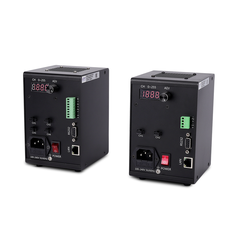
Stable constant-current control for spot and structure lights
LXV-3ACC provides adjustable current, RS232 communication and external triggering for compact machine-vision spot lights and the listed structure-light configurations.
- Drive mode
- Constant current
- Stable output and linearity
- Adjustment
- 256 levels
- Encoder or PC
- Current range
- 0–2500 mA
- Model-dependent
- Trigger
- 5–24 V
- High-level effective
- Communication
- RS232
- 19200 bps
Spot-light control
Choose a 350, 700, 1000, 1500 or 2500 mA family and match the required two- or four-channel configuration.
Structure-light control
Use the dedicated 12 V, 400 mA two-channel or 700 mA one-channel rows for the listed structure-light configurations.
Short-exposure imaging
Stable output current, good linearity and flash-free operation at low exposure time support repeatable imaging.
Host or trigger operation
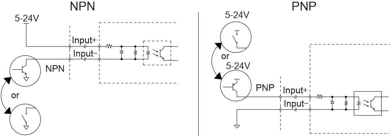
Adjust locally or through RS232, and coordinate illumination with a PLC or sensor through the 5–24 V input.
Do not select by channel count alone
Match light type, current range, total power, one-channel power, number of channels and dimension group from the same model row.
RS232 working system, operating parameters and trigger states
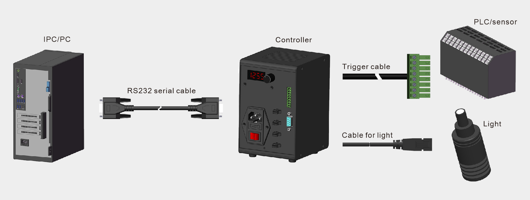
The host communicates through RS232 while the PLC or sensor uses a separate trigger cable; the controller powers the connected light through its light cable.
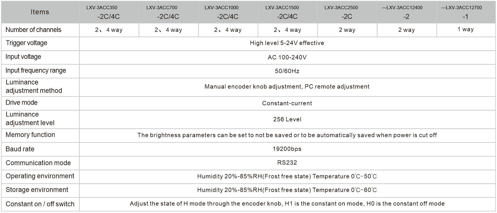
| Parameter | Operating value |
|---|---|
| Input supply | AC 100–240 V |
| Input frequency | 50/60 Hz |
| Drive mode | Constant current |
| Adjustment resolution | 256 levels |
| Adjustment methods | Manual encoder knob or PC remote adjustment |
| External trigger | High level 5–24 V effective |
| Communication | RS232 |
| Baud rate | 19200 bps |
| Memory behavior | Brightness can be set not to save or to save automatically at power off |
| H mode | H1 constant-on; H0 constant-off |
| Operating environment | 0–50 °C; 20–85% RH, frost-free |
| Storage environment | 0–60 °C; 20–85% RH, frost-free |
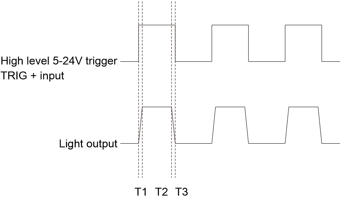
5–24 V high-level input with selectable constant state
In H1 constant-on mode, applying the high-level trigger turns the light off. In H0 constant-off mode, applying the high-level trigger turns the light on. T1, T2 and T3 mark the switching intervals shown in the waveform.
Select current, load and channels from all 11 controller rows
Spot-light models use the current-and-channel code; structure-light models additionally encode the 12 V output family.
- 1
Identify the light family
Separate spot-light and structure-light controller rows.
- 2
Match adjustable current
Use the range required by the connected light.
- 3
Check both power limits
Verify total and one-channel output in the same row.
- 4
Confirm channels and housing
Release the matching channel count and dimension group.
LXV-3ACC [max current]-[channels]CStructure-light modelLXV-3ACC 12 [max current]-[channels]- LXV
- LuxMV product prefix
- 3ACC
- Constant-current controller
- 12
- Structure-light output voltage code
- 350–2500
- One-channel maximum output current code
- 1 / 2 / 4
- Number of channels
| Application | Model | Adjustable current | Total power | One-channel maximum | Channels | Dimension | Trigger |
|---|---|---|---|---|---|---|---|
| Spot light | LXV-3ACC350-2C | 0–350 mA | 2 W | 1 W | 2 | 1 | 5–24 V |
| Spot light | LXV-3ACC350-4C | 0–350 mA | 4 W | 1 W | 4 | 1 | 5–24 V |
| Spot light | LXV-3ACC700-2C | 0–700 mA | 4 W | 2 W | 2 | 1 | 5–24 V |
| Spot light | LXV-3ACC700-4C | 0–700 mA | 8 W | 2 W | 4 | 1 | 5–24 V |
| Spot light | LXV-3ACC1000-2C | 0–1000 mA | 6 W | 3 W | 2 | 1 | 5–24 V |
| Spot light | LXV-3ACC1000-4C | 0–1000 mA | 12 W | 3 W | 4 | 1 | 5–24 V |
| Spot light | LXV-3ACC1500-2C | 0–1500 mA | 10 W | 5 W | 2 | 2 | 5–24 V |
| Spot light | LXV-3ACC1500-4C | 0–1500 mA | 20 W | 5 W | 4 | 2 | 5–24 V |
| Spot light | LXV-3ACC2500-2C | 0–2500 mA | 20 W | 10 W | 2 | 2 | 5–24 V |
| Structure light | LXV-3ACC12400-2 | 0–400 mA | 10 W | 5 W | 2 | 3 | 5–24 V |
| Structure light | LXV-3ACC12700-1 | 0–700 mA | 8.5 W | 8.5 W | 1 | 3 | 5–24 V |
Use the matching face layout, DIN base and service envelope
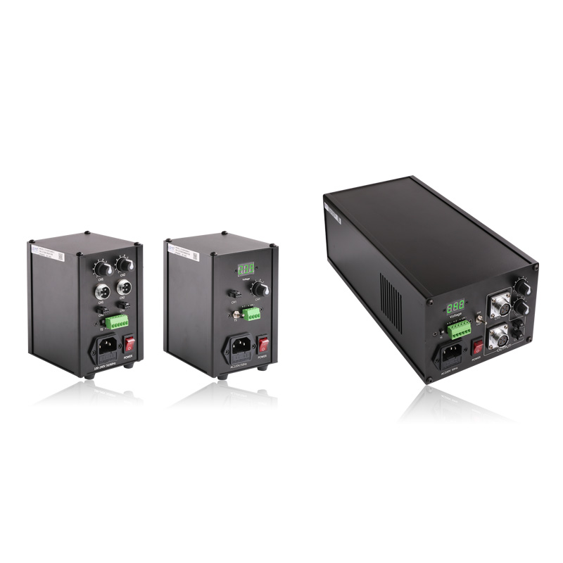
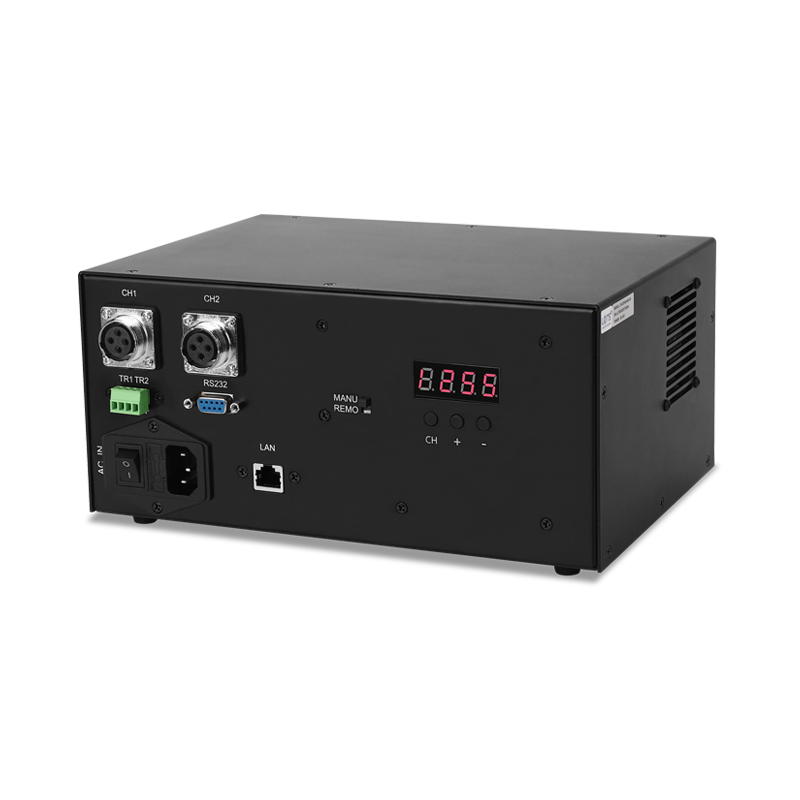
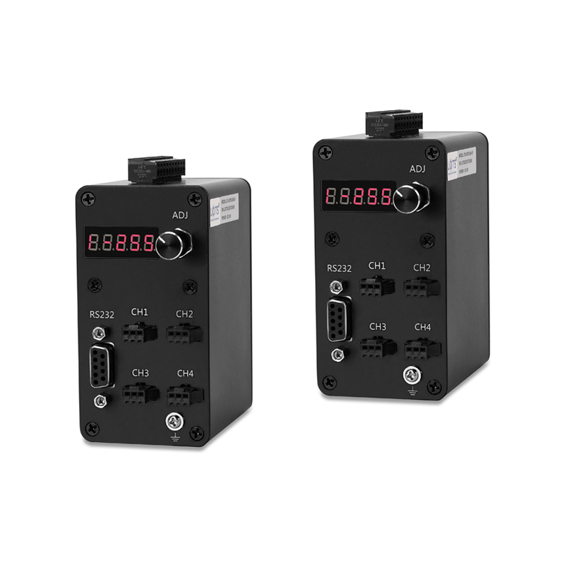
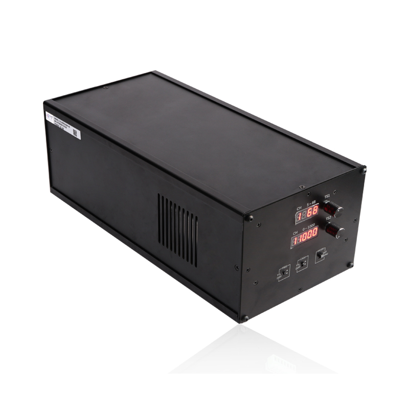
All three mechanical groups use compact upright enclosures, but the front interface and body depth differ with the selected product group.
| Group | Models | Overall width | Overall height | Overall depth | Mounting |
|---|---|---|---|---|---|
| 1 | 350 / 700 / 1000-2C / 4C | 100 mm | 156 mm | 134 mm | DIN guide-rail base; 4 × M3 after removal |
| 2 | 1500 / 2500-2C / 4C | 100 mm | 156 mm | 134 mm | DIN guide-rail base; 4 × M3 after removal |
| 3 | 12400-2 / 12700-1 | 100 mm | 156 mm | 110 mm | DIN guide-rail base; 4 × M3 after removal |
Confirm the dimension group before panel release
Use the shown DIN guide-rail base or remove it to access the four M3 mounting holes. Do not transfer a face layout between groups.
Reserve access to power, RS232, trigger and light outputs
Keep the encoder, display, AC input, communication connector, trigger terminal, channel outputs and cooling face reachable.