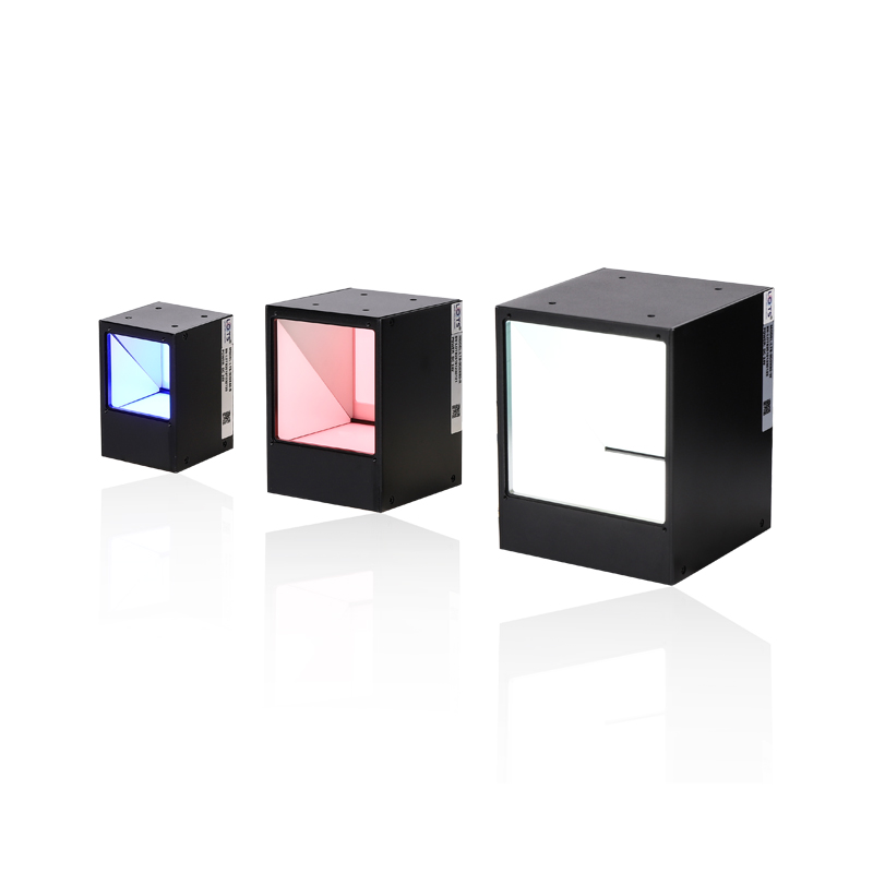
Compact coaxial illumination for reflective surfaces, print and stitch detail
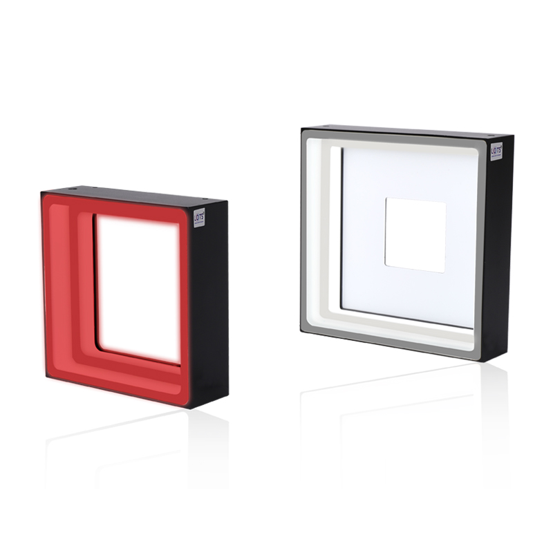
LXV-3COX is a compact, cost-effective coaxial-light series whose documented design raises luminance by 50% and reduces double images. Its protected cable entry resists pulling, and an optional guard plate keeps falling material or dust away from the emitting area.
- Standard models
- 8
- 20–120 mm emitting surfaces
- Luminance change
- +50%
- Documented series feature
- Supply
- 24 V
- Every standard model
- Power range
- 1.5–45.4 W
- Model and colour dependent
- Mass range
- 81–1023 g
- Model dependent
Chip and wafer damage
Use camera-axis illumination to reveal damage on reflective semiconductor surfaces.
Reflective-surface scratches
Reduce directional reflection and preserve shallow scratch contrast.
Barcodes and QR codes
Read printed marks on glossy or specular material.
Printing and silkscreen
Inspect character, registration and stitch detail with uniform background separation.
Measured optical behaviour, protected construction and stitch-inspection evidence
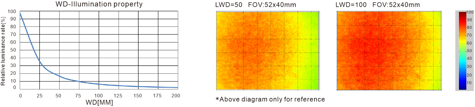
The catalogue documents one LXV-3COX50-W optical reference and a stitch-inspection instance using LXV-3COX40-W. Numerical conditions and construction choices are rebuilt as searchable HTML; only the curve, irradiance fields and product or result objects remain as source crops.
LXV-3COX50-W working-distance and uniformity reference
Relative luminance is plotted from 0 to 200 mm working distance. The two relative-irradiance fields use the same 52 × 40 mm field of view at LWD 50 mm and LWD 100 mm and share the displayed 10–100 scale.
Protected cable entry and configurable housing
The covered wire jacket is designed to resist pulling. Configurable items listed in the source are viewport, housing length and width, parallel film, combined light, colour or colour temperature, cable length and installation method; RGB three-colour construction can also be customised.
Optional emitting-area guard plate
The optional plate protects the emitting area from falling material or dust that could otherwise affect the illumination result.
Stitch-inspection instance
The documented example uses components as the workpiece and LXV-3COX40-W as the light. The result highlights the stitch and produces obvious contrast between the background and stitch.
Documented optical, construction and application conditions
| Reference | Condition | Documented value |
|---|---|---|
| Working-distance response | Model / plotted span | LXV-3COX50-W / 0–200 mm |
| Uniformity field 1 | LWD / FOV | 50 mm / 52 × 40 mm |
| Uniformity field 2 | LWD / FOV | 100 mm / 52 × 40 mm |
| Stitch inspection | Workpiece / light | Components / LXV-3COX40-W |
| Stitch inspection | Documented result | Highlighted stitch; obvious contrast |
| Guard plate | Function | Protects the emitting area from falling material and dust |
- Optical reference
- LXV-3COX50-W
- Uniformity fields
- LWD 50 / 100 mm
- Application light
- LXV-3COX40-W
- Protection
- Pull-resistant jacket; optional guard plate
Select emitting width, wavelength and electrical load as one verified row
Eight 24 V standard models run from LXV-3COX20 through LXV-3COX120. Red and G/B/W loads differ on six rows, so emitting size, colour, power, mass and drawing number must remain attached to the selected model.
- 1
Define the reflective feature
Record the scratch, code, print or stitch that must separate from the background.
- 2
Choose emitting width
Select the smallest 20, 30, 40, 50, 60, 80, 100 or 120 mm field that covers the camera view.
- 3
Validate wavelength
Test red, green, blue or 6600 K white on the real target; UV and IR are custom options.
- 4
Match controller and load
Use the exact 24 V colour-dependent load with a strobe, analog or digital controller.
Read the product model pattern
LXV-3COX##-R/G/B/W/IR/UV- LXV
- Product prefix
- 3COX
- Coaxial light
- ##
- Width of emitting area
- R/G/B/W
- Standard colour code
- IR/UV
- Custom wavelength option
LXV-3COX complete standard model range
Every dimension and electrical value remains attached to its own model row.
| Model | Color | Dimension | Voltage | Power |
|---|---|---|---|---|
| LXV-3COX20-R/BGW | Custom colour | 54xW30xH30(mm) | 24V | 1.5W/1.5W |
| LXV-3COX30-R/BGW | Custom colour | 64xW40xH40(mm) | 24V | 2.9W/4.4W |
| LXV-3COX40-R/BGW | Custom colour | 74xW50xH50(mm) | 24V | 4.4W/4.4W |
| LXV-3COX50-R/BGW | Custom colour | 84xW60xH60(mm) | 24V | 6.5W/7.2W |
| LXV-3COX60-R/BGW | Custom colour | 94xW70xH70(mm) | 24V | 8.7W/10.8W |
| LXV-3COX80-R/BGW | Custom colour | L114W92xH90(mm) | 24V | 15.2W/21.6W |
| LXV-3COX100-R/BGW | Custom colour | 134xW112xH110(mm) | 24V | 24.5W/32.4W |
| LXV-3COX120-R/BGW | Custom colour | 154xW132xH130(mm) | 24V | 34.6W/45.4W |
Complete standard-model electrical reference
Power, mass and drawing number are copied from the product-specific table and must not be transferred between models.
| Model | Supply | Red power | G / B / W power | Mass | Adapted controller | Drawing | Common |
|---|---|---|---|---|---|---|---|
| LXV-3COX20 | 24 V | 1.5 W | 1.5 W | 81 g | Strobe / analog / digital | 1 | Y |
| LXV-3COX30 | 24 V | 2.9 W | 4.4 W | 133 g | Strobe / analog / digital | 2 | Y |
| LXV-3COX40 | 24 V | 4.4 W | 4.4 W | 198 g | Strobe / analog / digital | 3 | Y |
| LXV-3COX50 | 24 V | 6.5 W | 7.2 W | 268 g | Strobe / analog / digital | 4 | Y |
| LXV-3COX60 | 24 V | 8.7 W | 10.8 W | 370 g | Strobe / analog / digital | 5 | Y |
| LXV-3COX80 | 24 V | 15.2 W | 21.6 W | 613 g | Strobe / analog / digital | 6 | Y |
| LXV-3COX100 | 24 V | 24.5 W | 32.4 W | 938 g | Strobe / analog / digital | 7 | Y |
| LXV-3COX120 | 24 V | 34.6 W | 45.4 W | 1023 g | Strobe / analog / digital | 8 | Y |
Preserve the coaxial path and install the exact 20–120 mm housing
Three independently cropped drawing groups retain all eight complete catalogue drawings without splitting a product drawing. Every illustrated model has a 500 mm lead and a 4-M3 depth 4.5 mounting callout.
- 01
Use only the drawing and dimensions for the exact selected model.
- 02
Centre the camera, coaxial optics and reflective target on one axis.
- 03
Keep the viewport, emitting aperture and optional guard plate clear of brackets.
- 04
Reserve the shown 500 mm lead, cable bend and service access before release.
Spectral, environmental and service reference
| Item | Verified value |
|---|---|
| Red peak wavelength | 620–630 nm |
| Green peak wavelength | 525–530 nm |
| Blue peak wavelength | 465–470 nm |
| White colour temperature | 6600 K |
| Custom wavelength | UV and IR available as required |
| Operating environment | 0–40 °C; 20–85% RH, non-condensing |
| Life-span definition | 50,000 h at 50% luminance reduction from factory default |
| Value-added service | One year free technical support; sample free rent |
Configuration and cable choices
| Item | Documented choice or use |
|---|---|
| Configurable optical and mechanical items | Viewport; housing length and width; parallel film; combined light; colour or colour temperature; cable length; installation method |
| Custom colour | RGB three-colour construction can be customised |
| PVC extension cable | High flexibility, bending resistance and high-temperature resistance; intended inside equipment |
| High-flexibility extension cable | Harder and more abrasion resistant than PVC; intended for drag-chain production lines |
Mechanical envelope by model
| Model | Emitting surface | Optical opening | Body face | Housing length | Mounting reference | Lead |
|---|---|---|---|---|---|---|
| LXV-3COX20 | 20 × 20 mm | 16 mm | 30 × 30 mm | 54 mm | 12 × 10 mm hole spacing; 4-M3 depth 4.5 | 500 mm |
| LXV-3COX30 | 30 × 30 mm | Not separately stated | 40 × 40 mm | 64 mm | 20 × 16 mm hole spacing; 4-M3 depth 4.5 | 500 mm |
| LXV-3COX40 | 40 × 40 mm | 33 mm | 50 × 50 mm | 74 mm | 30 × 25 mm hole spacing; 4-M3 depth 4.5 | 500 mm |
| LXV-3COX50 | 50 × 50 mm | 38 mm | 60 × 60 mm | 84 mm | 30 × 25 mm hole spacing; 4-M3 depth 4.5 | 500 mm |
| LXV-3COX60 | 60 × 60 mm | 43 mm | 70 × 70 mm | 94 mm | 30 × 40 mm hole spacing; 4-M3 depth 4.5 | 500 mm |
| LXV-3COX80 | 80 × 80 mm | 70 mm | 92 × 90 mm | 114 mm | 50 × 60 mm hole spacing; 4-M3 depth 4.5 | 500 mm |
| LXV-3COX100 | 100 × 100 mm | 76 mm | 112 × 110 mm | 134 mm | 70 × 80 mm hole spacing; 4-M3 depth 4.5 | 500 mm |
| LXV-3COX120 | 120 × 120 mm | 96 mm | 132 × 130 mm | 154 mm | 90 × 100 mm hole spacing; 4-M3 depth 4.5 | 500 mm |
Product content is transcribed and reorganised from the verified LXV 2025 catalogue page 73. Values are model-specific; do not transfer power, mass or dimensions between rows.
Verify optical result, exact model and installation together
- Target, defect and required contrast
- Field, direction and working distance
- Exact voltage or current and controller load
- Mounting, cable and thermal clearance