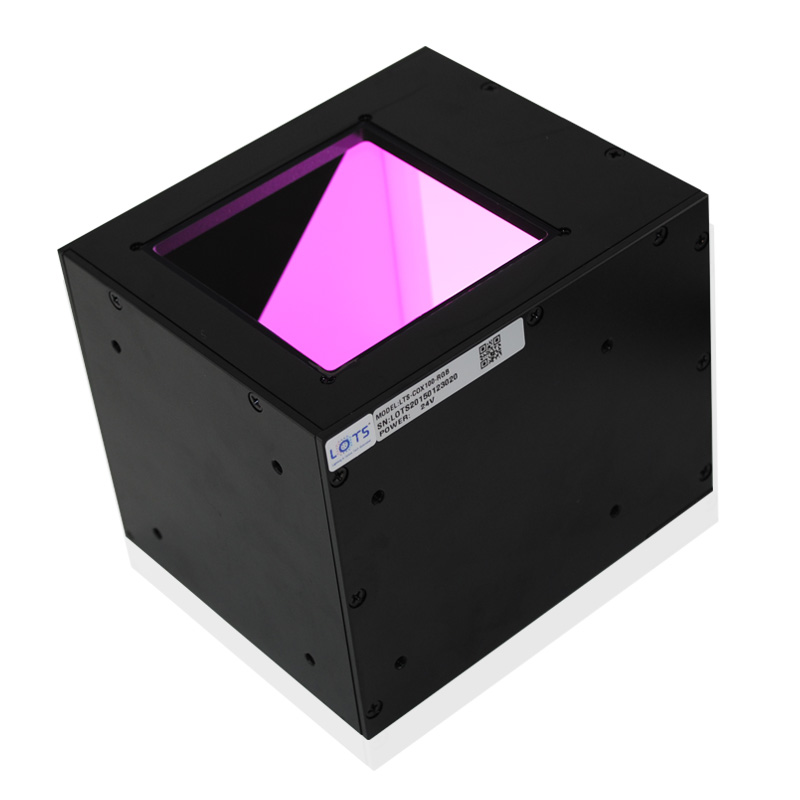
Independently controlled dual- and triple-colour coaxial illumination
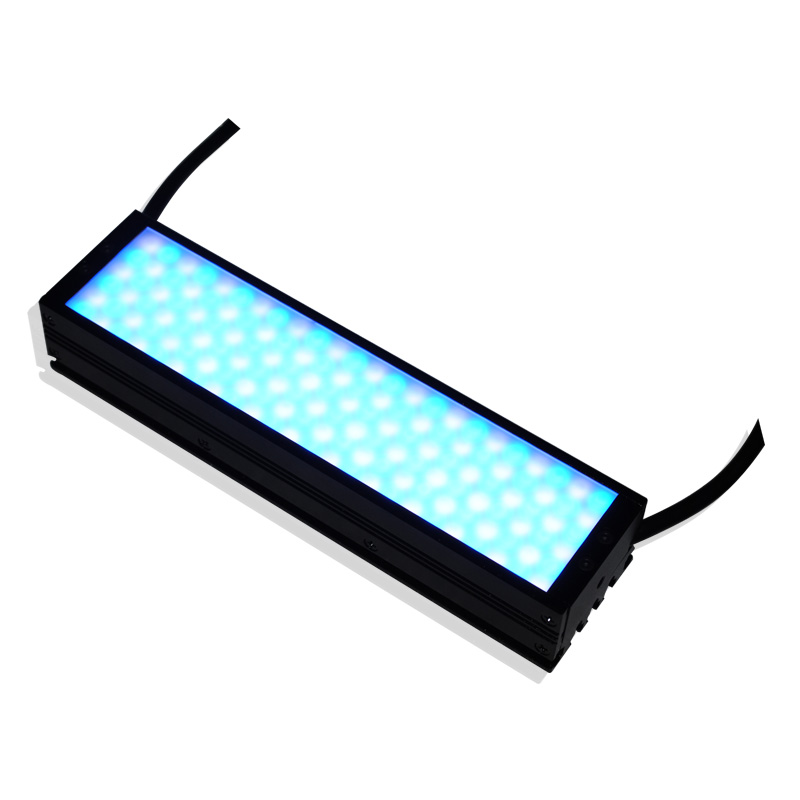
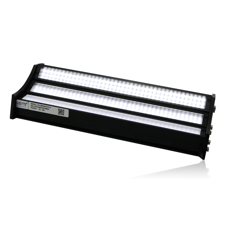
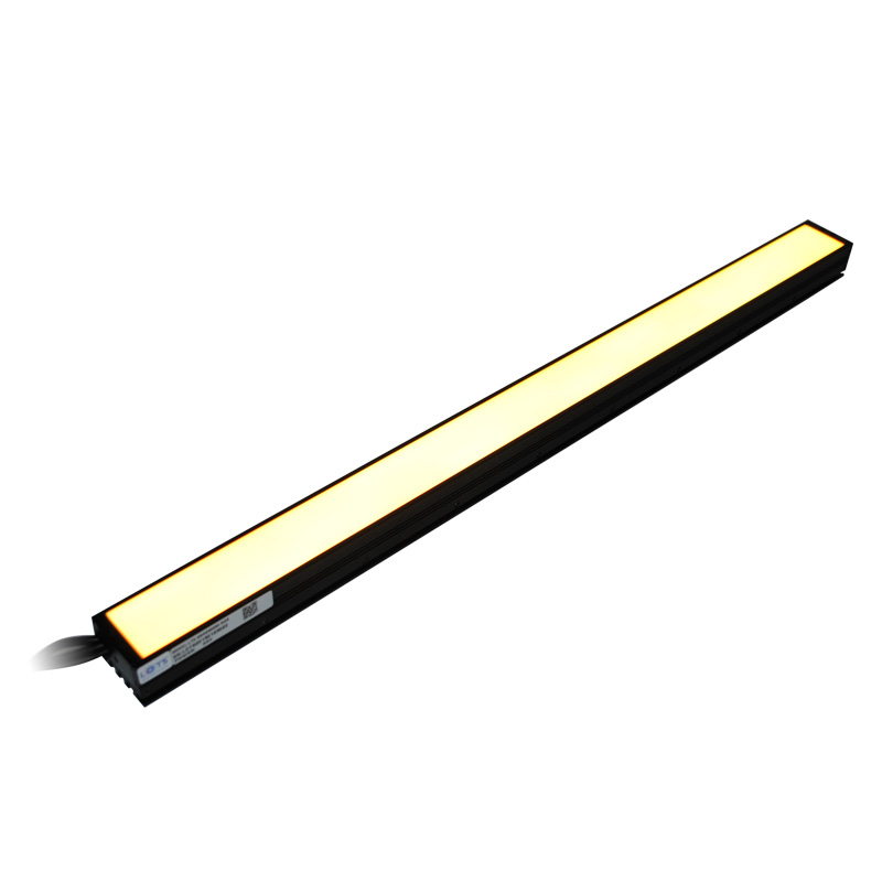
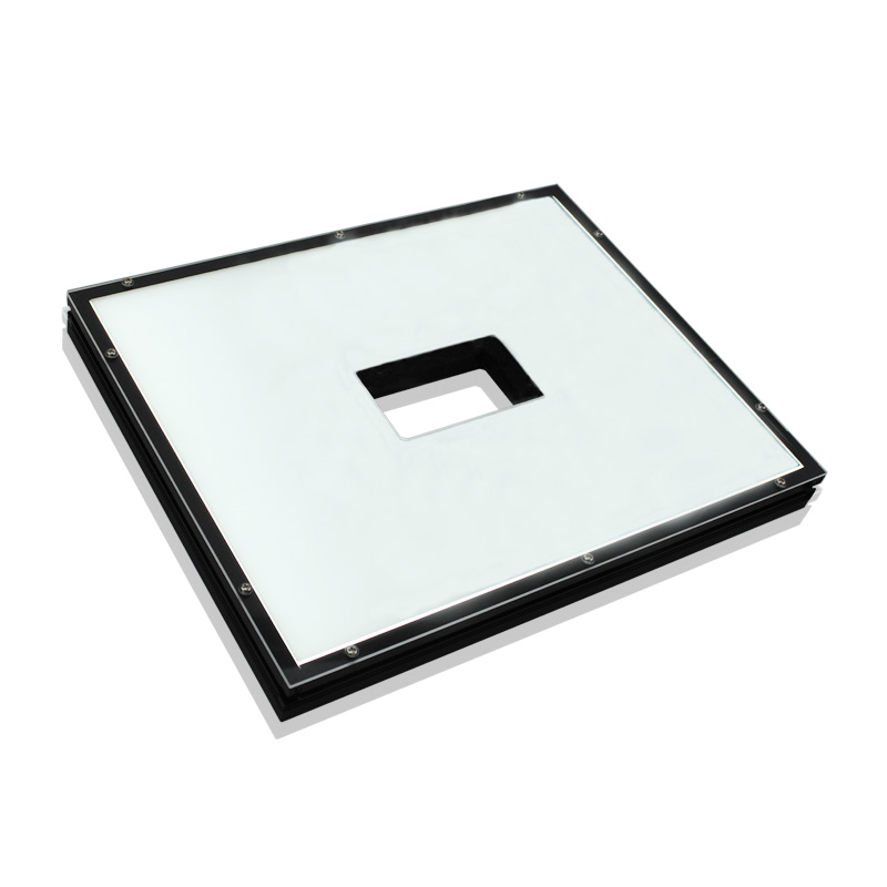
LXV-COX uses dense LED arrays in a coaxial optical path so the camera and illumination share the target normal. The documented BW model combines blue and white channels; the RGB model provides independently controllable red, green and blue channels for switching or mixing spectral response without moving the fixture.
- Documented models
- 2
- BW and RGB channel sets
- Supply
- 24 V
- Both model rows
- Independent control
- Per colour channel
- Switch or mix output
- Inspection modes
- Colour patterns / PCB
- Axial illumination
Colour-pattern inspection
Switch or mix channels to separate coloured print, coating and registration differences.
Circuit-board inspection
Use the blue/white coaxial field to illuminate flat conductive and printed structures along the camera axis.
Reflective planar parts
Reduce directional shadows by placing illumination on the viewing axis.
Spectral-response comparison
Capture the same target under separate channels and retain the response that best separates the required feature.
How the optical structure solves the inspection problem
Review the product-specific optical behavior, confirmed values and technical graphics together before selecting the final configuration.
- Dense coaxial array
- Closely arranged emitters feed a shared coaxial path for a broad axial field.
- Blue and white model
- LXV-COX13752-BW combines blue and white LED arrays without reducing the stated brightness and uniformity.
- RGB model
- LXV-COX100-RGB provides red, green and blue primary-colour channels.
- Independent intensity
- Each colour can be controlled separately, allowing colour changes without replacing or repositioning the light.
- Model-specific mechanics
- The BW and RGB designs have different housing envelopes and electrical loads; their values are not interchangeable.
Select from the actual optical, mechanical and electrical requirement
Do not select a custom light from appearance alone. Confirm target, contrast, field, interfaces and load together.
- 1
Define the colour task
Identify the print, coating, PCB feature or material response that must be separated.
- 2
Test channels independently
Compare each available colour at the same camera position before selecting a mixture.
- 3
Choose the exact body
Use 147 × 87 × 60 mm for LXV-COX13752-BW or 134 × 114 × 108 mm for LXV-COX100-RGB.
- 4
Size controller outputs
Provide one independently adjustable output for every colour channel in use.
- 5
Validate the recipe
Record per-channel intensity, camera exposure and acceptance samples under production conditions.
Read the product model pattern
LXV-COX[size]-[channels]- LXV
- Product prefix
- COX
- Multi-colour coaxial-light family
- Size
- Model-specific optical or body code
- BW / RGB
- Blue-white or red-green-blue channel set
LXV-COX model range
Values remain attached to their own model and are not transferred between designs.
| Model | Channels | Boundary | Emitting reference | Voltage | Power |
|---|---|---|---|---|---|
| LXV-COX13752-BW | Blue + white | L147 × W87 × H60 mm | 137 × 52 mm; 48 × 133 mm | 24 V | 8.6 W |
| LXV-COX100-RGB | Red + green + blue | L134 × W114 × H108 mm | Use model drawing for aperture and field | 24 V | 21.8 W |
Release the exact product drawing with the complete inspection station
Dimensions, openings, mounting, channels and thermal clearances belong to the selected product only.
- 01
Align the camera and target normal through the coaxial optical axis; keep the emitting field and camera path unobstructed.
- 02
For LXV-COX13752-BW, reserve the complete 147 × 87 × 60 mm body and both 137 × 52 mm and 48 × 133 mm emitting-surface references.
- 03
Fasten the BW body only at the documented mounting groups: six M3 holes with 4 mm maximum engagement and two groups of four M3 holes with 4 mm maximum engagement.
- 04
Route the documented 500 mm lead without loading the connector or crossing the optical field.
- 05
Wire blue/white or RGB channels to separate controller outputs; never parallel channels unless the selected controller and final wiring specification permit it.
- 06
Provide 24 V and the exact model load—8.6 W for BW or 21.8 W for RGB—then validate colour balance, uniformity and housing temperature at production duty.
Confirm design values and real inspection performance together
- Target, defect and required contrast
- Camera, lens, field and working distance
- Exact model voltage, power and channels
- Boundary, mounting, cable and cooling clearance