Uniform dome illumination for reflective, uneven and pin-inspection targets
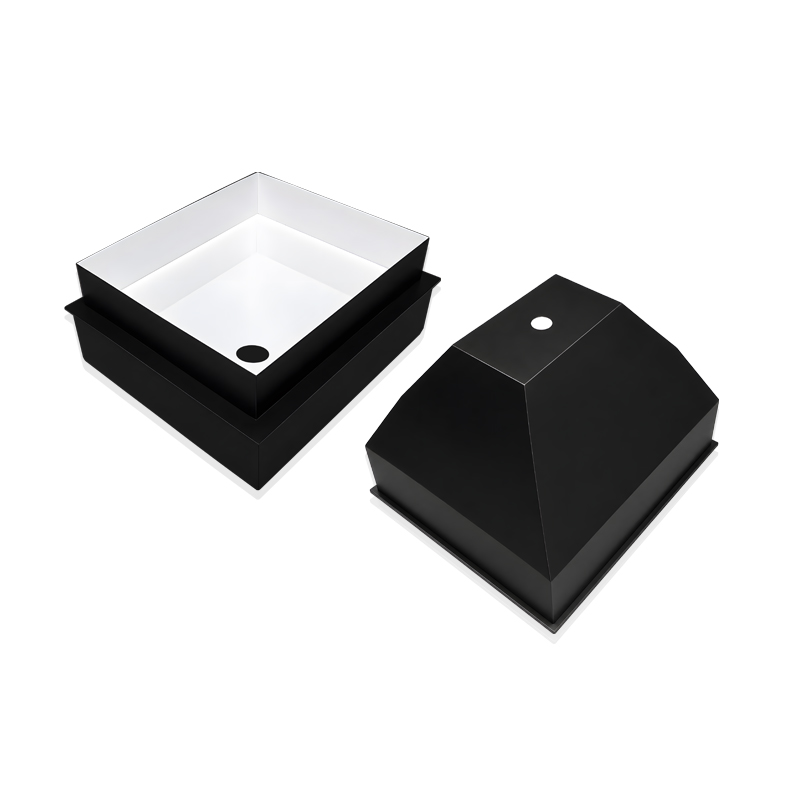
LXV-DM surrounds the target with diffuse dome illumination to reduce directional reflection and shadowing. Seven 24 V standard diameters cover 50–230 mm housings, while shape, opening, spectrum, channel layout, cable and mounting can be configured for the inspection geometry.
- Standard models
- 7
- DM50 through DM230
- Supply
- 24 V
- Every standard row
- Power
- 1.5–49.0 W
- Model and colour dependent
- Optical reference
- LXV-DM120-W
- Curve and two field maps
- Custom RGB example
- LXV-DM400-RGB
- 69.1 W · three independent colours
Reflective-surface inspection
Use diffuse multi-direction light to reduce dominant highlights on glossy or metallic surfaces.
Uneven-surface inspection
Wrap illumination around height and slope changes so local features remain visible from multiple directions.
Cigarette-pack printing
Maintain readable printed contrast over reflective or slightly uneven packaging.
Metal scratches and component pins
Reveal shallow surface defects and distinguish flat bright pins from uneven dark pins in the documented DM120-W example.
DM120-W working-distance response, uniformity fields and complete pin-inspection evidence
The optical reference combines a 0–150 mm relative-luminance curve with separate LWD 10 and LWD 20 irradiance fields. The pin example keeps the camera arrangement, transformer-like component workpiece and final contrast result as three independent objects.
LXV-DM120-W optical references
Configurable dome construction
PIN inspection · LXV-DM120-W
Independent custom record · LXV-DM400-RGB
- Optical model
- LXV-DM120-W
- Curve range
- WD 0–150 mm · relative luminance 0–100%
- Uniformity fields
- LWD 10 · FOV 60 × 45 mm / LWD 20 · FOV 66 × 50 mm
- Application result
- Flat pin is white · uneven pin is black
- Standard range
- LXV-DM50 / 70 / 100 / 120 / 154 / 180 / 230
- Separate custom record
- LXV-DM400-RGB · 24 V · 69.1 W
Choose one complete diameter, aperture and colour-power row
All seven standard rows use 24 V, but their emitting diameters, camera openings, depth, mounting, red load, green/blue/white load and mass differ. The 400 mm RGB dome is a separate customized configuration and is not a standard-row substitute.
LXV-DM400-RGB is an independent customized 400 mm triple-colour configuration. Its 69.1 W load, three-channel construction and mechanical drawing must not be transferred to DM50–DM230. Shape, outer and inner diameter, combined-light arrangement, colour or colour temperature, multi-area control, cable length and installation method are project-specific options.
- 1
Define the reflective target
Record the complete field, height variation, surface finish, defect and pin or print feature that must remain visible.
- 2
Fit the dome and camera opening
Choose an outer diameter and aperture that surround the target without obstructing the lens sight line.
- 3
Choose spectrum and controller capacity
Test R, G, B, 6600 K white or a confirmed custom wavelength, then size the strobe, analog or digital controller from the exact colour load.
- 4
Validate the complete optical build
Confirm uniformity, exposure, glare control, cable path, temperature and acceptance criteria on production-representative parts.
Read the product model pattern
LXV-DM##-R/G/B/W/IR/UV- LXV
- Product prefix
- DM
- Customized dome light
- ##
- Dome diameter identifier
- R/G/B/W/IR/UV
- Colour or wavelength code
LXV-DM model and optical selection tables
Each value remains attached to its own model or lens row.
Standard LXV-DM models
| Model | Voltage | Power · R | Power · G/B/W | Weight | Drawing | Common |
|---|---|---|---|---|---|---|
| LXV-DM50 | 24 V | 1.5 W | 2.2 W | 58 g | 1 | Y |
| LXV-DM70 | 24 V | 2.2 W | 2.9 W | 106 g | 2 | Y |
| LXV-DM100 | 24 V | 7.2 W | 8.0 W | 183 g | 3 | Y |
| LXV-DM120 | 24 V | 12.3 W | 15.2 W | 264 g | 4 | Y |
| LXV-DM154 | 24 V | 14.4 W | 18.0 W | 522 g | 5 | Y |
| LXV-DM180 | 24 V | 21.6 W | 27.4 W | 673 g | 6 | Y |
| LXV-DM230 | 24 V | 38.9 W | 49.0 W | 1337 g | 7 | Y |
Spectrum, control and operating conditions
| Item | Product value | Selection meaning |
|---|---|---|
| Visible output | Red 620–630 nm · Green 525–530 nm · Blue 465–470 nm · White 6600 K | Keep the colour choice attached to its red or G/B/W power value |
| Adapted controllers | Strobe / analog / digital controller | Match operating mode and total connected load |
| Optional wavelengths | UV and IR can be customized | Confirm wavelength, output and safety before release |
| Operating environment | 0–40 °C · 20–85% RH without condensation | Verify both temperature and humidity at the installation |
| Reference life | 50,000 h at the stated 50% luminance condition | Use as a reference condition rather than a universal guarantee |
| PVC extension cable | Flexible, bend- and heat-resistant; intended inside equipment | Use where drag-chain duty is not required |
| High-flex extension cable | Harder and more abrasion-resistant; intended for drag-chain lines | Reserve the correct bend radius and travel path |
Native mechanical envelope
| Model | Outer / emitting diameter | Camera opening | Depth / rear port | Mounting and cable |
|---|---|---|---|---|
| LXV-DM50 | Ø50 / Ø25 mm | Ø12 / Ø17 mm | 30.5 mm / Ø22 mm | 4-M3 depth 4 at 45° · 500 mm lead |
| LXV-DM70 | Ø70 / Ø45 mm | Ø15 / Ø32 mm | 32 mm / Ø42 mm | 4-M3 depth 4 at 45° · 500 mm lead |
| LXV-DM100 | Ø100 / Ø66 mm | Ø25 / Ø33 mm | 42 mm / Ø40 mm | 4-M3 depth 4 · 500 mm lead |
| LXV-DM120 | Ø120 / Ø78 mm | Ø40 / Ø30 mm | 52 mm / Ø51 mm | 4-M3 depth 5 · 500 mm lead |
| LXV-DM154 | Ø154.5 / Ø114 mm | 50 mm square / Ø55 mm | 66 mm / Ø73 mm | 4-M3 depth 4 · 500 mm lead |
| LXV-DM180 | Ø180 / Ø130 mm | Ø50 / Ø35 mm | 12 + 93 mm / Ø60 mm | 4-M4 depth 5 · 500 mm lead |
| LXV-DM230 | Ø230 / Ø150 mm | Ø35 / Ø80 mm | 111 mm / Ø95 mm | 4-M6 depth 8 · 500 mm lead |
LXV-DM400-RGB customized record
| Model | Voltage | Power | Construction | Mechanical reference | Applications |
|---|---|---|---|---|---|
| LXV-DM400-RGB | 24 V | 69.1 W | Three primary-colour LED arrays; each colour controlled independently | Ø400 body · Ø350 emitting surface · 202.5 mm depth · Ø150 rear port | Beverage-cap inspection · can inspection |
Install the exact standard dome drawing or the separate DM400-RGB customized envelope
Seven independently bounded standard drawings keep each model’s emitting surface, camera opening, rear port, fasteners and 500 mm lead together. The customized 400 mm RGB drawing remains separate so its 202.5 mm depth and six-point mounting are not confused with the standard range.
- 01
Match the exact model code to drawing 1–7 or the separately identified DM400-RGB custom drawing.
- 02
Centre the lens through the documented camera opening and keep the dome axis aligned with the target field.
- 03
Reserve the complete depth, rear-port, connector, 500 mm lead and fastener access for the chosen enclosure.
- 04
Verify the selected colour load, controller channels, temperature, uniformity and inspection result together before release.
Verify model, optical result and mechanical fit together
- Exact product model and colour
- Working distance and camera field
- Voltage, power and controller
- Mounting, cable and thermal clearance