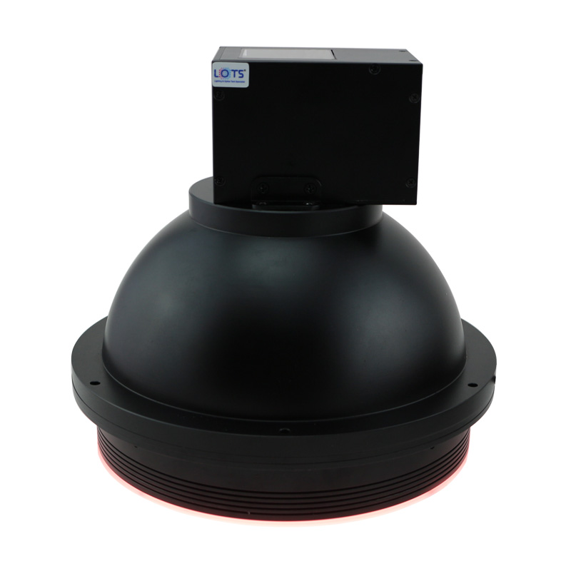
Three-channel coaxial, dome and ring light in one inspection assembly
LXV-DZGY3 closely integrates coaxial, dome and ring illumination into one Ø200 × 180 mm assembly. Each light path can be controlled separately so a can or other cylindrical part can be inspected for contour, relief, surface, sealant, pull-ring and printed-pattern defects without changing the fixture.
- Model
- LXV-DZGY3
- Single documented design
- Boundary
- Ø200 × H180 mm
- Ø180 inner reference
- Supply
- 24 V
- 24.7 W
- Light paths
- Coaxial / dome / ring
- Separately controlled
Inner and outer contour roundness
Use the combined circular field to check whether the can opening and outside edge remain concentric and round.
Edge depression and indentation
Add the ring response to reveal local height and edge-shape changes.
Surface scratches
Compare coaxial, diffuse dome and angled ring responses on the cylindrical finish.
Internal sealant defects
Use the available directions to reveal scratches and stains in the inner sealing region.
Ring-pull outline
Separate pull-ring boundary and relief from the can top.
Characters and patterns
Use the coaxial and diffuse channels to inspect printed surface information while controlling glare.
How the optical structure solves the inspection problem
Review the product-specific optical behavior, confirmed values and technical graphics together before selecting the final configuration.
- Coaxial channel
- Provides on-axis response for flat reflective characters, patterns and surface detail.
- Dome channel
- Surrounds the target with diffuse illumination to reduce directional hot spots on curved metal.
- Ring channel
- Adds angled light for rim, pull-ring, depression and relief contrast.
- Independent control
- Each path can be evaluated alone and then blended only when the combined image improves the required defect.
- Shared mechanical axis
- All three paths are held in one customised housing to preserve registration between inspection recipes.
Select from the actual optical, mechanical and electrical requirement
Do not select a custom light from appearance alone. Confirm target, contrast, field, interfaces and load together.
- 1
List every defect class
Separate contour, depression, scratch, sealant, pull-ring and print requirements before tuning.
- 2
Capture each channel alone
Record coaxial, dome and ring images at the same camera position and production exposure.
- 3
Choose a minimal blend
Combine only the paths that materially improve defect separation and repeatability.
- 4
Check the full envelope
Reserve Ø200 × H180 mm and keep the Ø180 internal field clear.
- 5
Match the controller
Provide three independently adjustable outputs and store a validated setting for each inspection recipe.
Read the product model pattern
LXV-DZGY3- LXV
- Product prefix
- DZGY
- Coaxial-dome-ring combined family
- 3
- Three separately controlled light paths
LXV-DZGY3 model range
Values remain attached to their own model and are not transferred between designs.
| Model | Light paths | Boundary | Inner / emitting references | Mounting | Voltage | Power |
|---|---|---|---|---|---|---|
| LXV-DZGY3 | Coaxial + dome + ring | Ø200 × H180 mm | Ø180 inner; Ø130 and 50 mm emitting references | 6 × Ø4.2 through holes on Ø190 reference | 24 V | 24.7 W |
Release the exact product drawing with the complete inspection station
Dimensions, openings, mounting, channels and thermal clearances belong to the selected product only.
- 01
Centre the camera, combined light and can on the same vertical axis; keep the Ø180 internal field and Ø130 emitting reference unobstructed.
- 02
Reserve the full Ø200 × H180 mm boundary and the 167 mm side-view emitting reference.
- 03
Fasten through the six Ø4.2 through holes on the Ø190 mounting reference without distorting the circular housing.
- 04
Keep both 50 mm emitting-surface references clear around the plan view and avoid fixtures that shadow one channel.
- 05
Route the documented 500 mm connection clear of the target, camera path and moving parts.
- 06
Provide 24 V / 24.7 W capacity, connect coaxial, dome and ring paths separately, then validate contrast and temperature at production duty.
Confirm design values and real inspection performance together
- Target, defect and required contrast
- Camera, lens, field and working distance
- Exact model voltage, power and channels
- Boundary, mounting, cable and cooling clearance