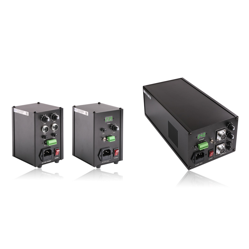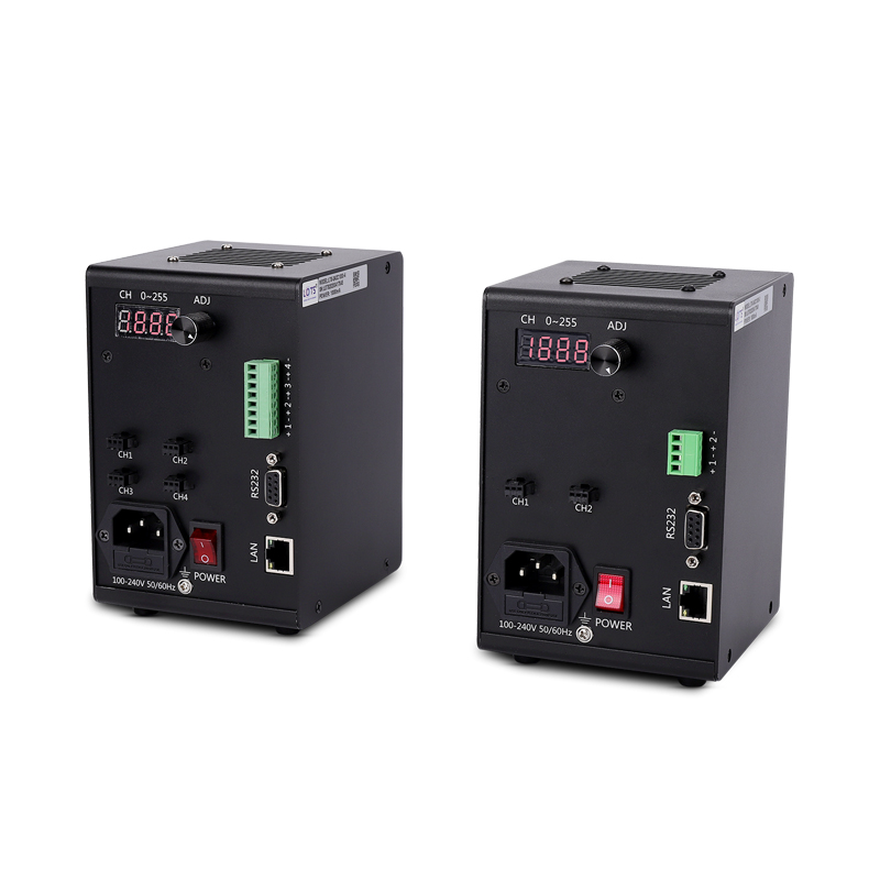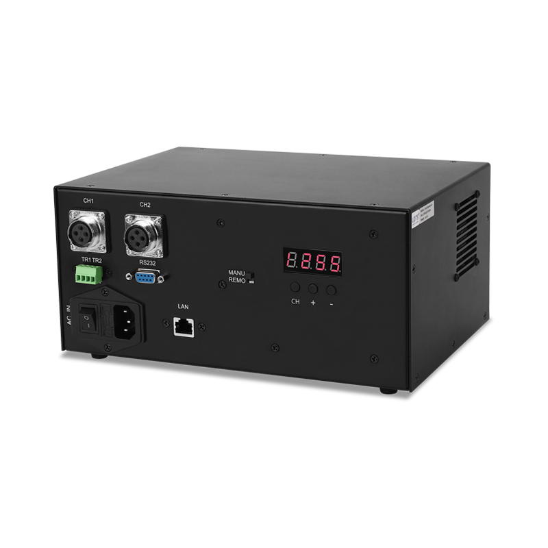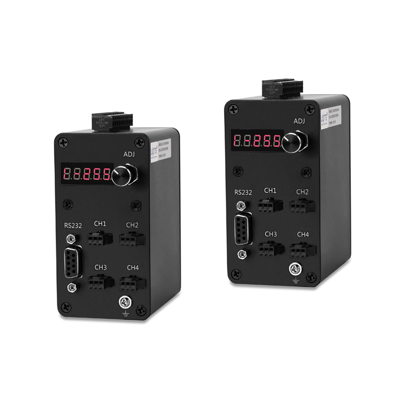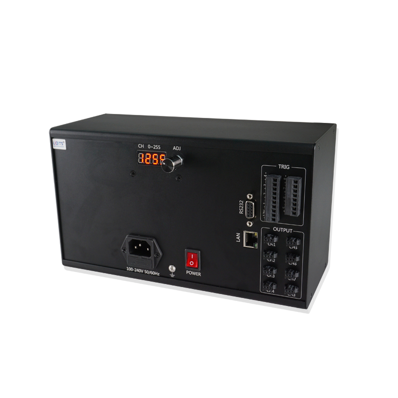
Dust-proof control for machine-vision lighting systems
The LXV-IP family combines Level 5 dust-proof construction with either digital eight-channel control or manual single-channel analogue control for dusty environments.
- Protection
- IP5X
- Source-stated dust protection
- Input
- AC 100–240 V
- All listed models
- Output
- 24 V
- 120–480 W by model
- Channels
- 1 or 8
- Analogue or digital
- Control
- Local / remote
- Model-dependent
Dusty production areas
Use the source-stated IP5X construction where dust exposure makes a standard controller enclosure unsuitable.
Eight-channel digital control
Select a 3DPC model for RS232/LAN communication, 256-level adjustment, power-off memory and external triggering.
Single-channel manual control
Select an APC model when one 240 W or 480 W channel and manual stepless adjustment match the connected light.
Machine-triggered capture
The two digital rows accept a 5–24 V high-level input and state support for external triggering up to 30 kHz.
Digital and analogue rows are different control architectures
Do not transfer communication, trigger or channel functions from the 3DPC rows to the APC rows. Select every electrical and mechanical value from one complete model row.
System topology, operating parameters and digital trigger behavior
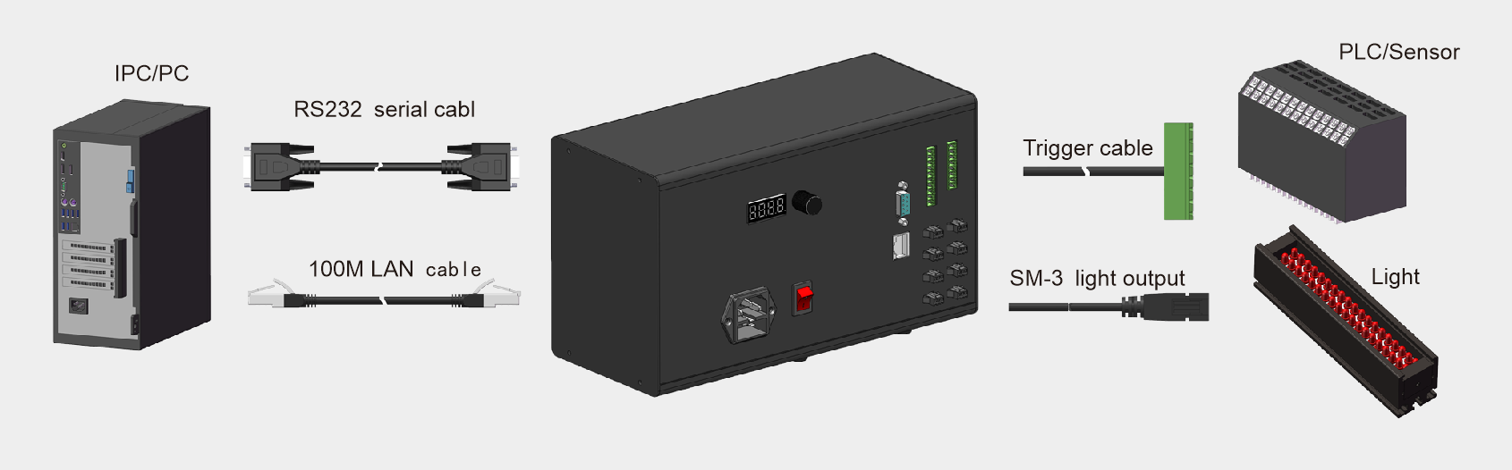
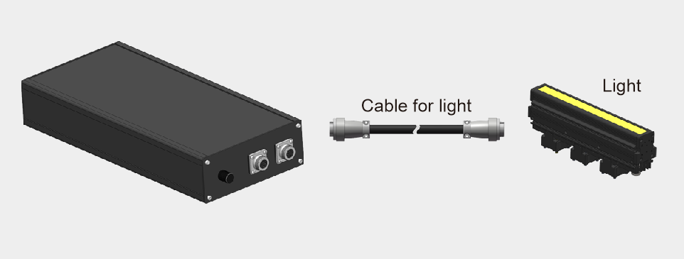
The digital configuration separates host communication, PLC/sensor triggering and the light-output cable. The analogue configuration uses a direct controller-to-light connection.
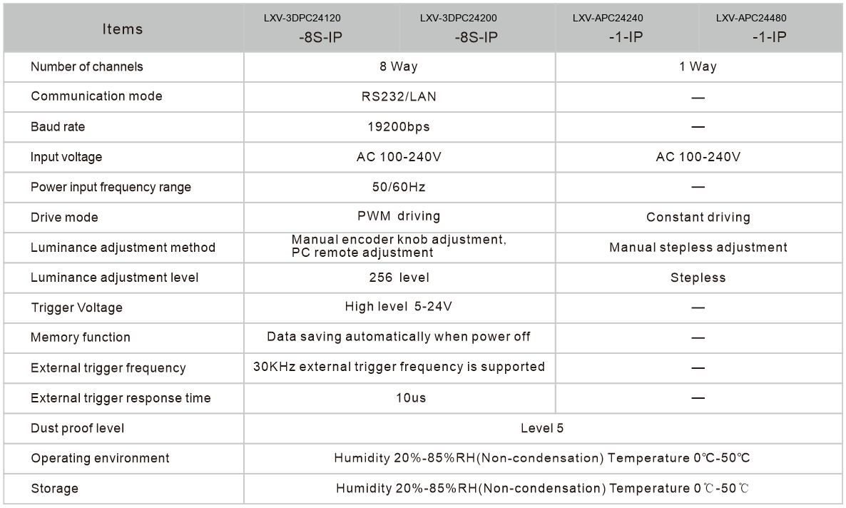
| Parameter | Digital 3DPC rows | Analogue APC rows |
|---|---|---|
| Channels | 8 | 1 |
| Communication | RS232 / LAN | — |
| Baud rate | 19200 bps | — |
| Input supply | AC 100–240 V | AC 100–240 V |
| Input frequency | 50/60 Hz | — |
| Drive mode | PWM driving | Constant driving |
| Adjustment | Manual encoder knob or PC remote | Manual stepless adjustment |
| Adjustment levels | 256 levels | Stepless |
| Trigger voltage | High level 5–24 V | — |
| Power-off memory | Automatic data saving | — |
| External trigger | 30 kHz supported; 10 μs response | — |
| Dust-proof level | Level 5 | Level 5 |
| Operating environment | 0–50 °C; 20–85% RH, non-condensing | 0–50 °C; 20–85% RH, non-condensing |
| Storage environment | 0–50 °C; 20–85% RH, non-condensing | 0–50 °C; 20–85% RH, non-condensing |
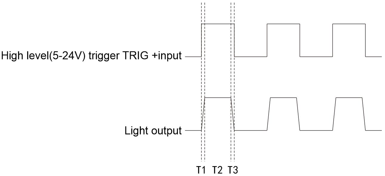
H1 constant-on and H0 constant-off modes
In H1 mode, a 5–24 V high-level signal turns the light off. In H0 mode, the same high-level signal turns the light on. T1 is turn-on delay, T2 is lighting time and T3 is turn-off delay; the source states T1 ≤ 10 μs and T3 ≤ 10 μs.
Choose one of four dust-proof controller configurations
The model code combines controller architecture, voltage, total power, channel count and dust-proof suffix.
- 1
Choose the architecture
Use 3DPC for eight-channel digital control or APC for one-channel manual control.
- 2
Verify each channel
Keep each connected light within the row’s one-channel maximum.
- 3
Verify total load
Keep the combined active load within the same row’s total output.
- 4
Release the exact housing
Use dimension group 1, 2 or 3 from that model row.
LXV-[3DPC/APC][voltage][total power]-[channels]-IP- LXV
- Product prefix
- 3DPC / APC
- Digital or analogue dust-proof controller
- 24
- Output-voltage code
- 120–480
- Total-power code
- 1 / 8
- Number of channels
- IP
- Dust-proof suffix
| Model | Output | Total power | One-channel max. | Channels | Dimension | Trigger |
|---|---|---|---|---|---|---|
| LXV-3DPC24120-8S-IP | 24 V | 120 W | 60 W | 8 | 1 | 5–24 V |
| LXV-3DPC24200-8S-IP | 24 V | 200 W | 60 W | 8 | 1 | 5–24 V |
| LXV-APC24240-1-IP | 24 V | 240 W | 240 W | 1 | 2 | — |
| LXV-APC24480-1-IP | 24 V | 480 W | 480 W | 1 | 3 | — |
Match the selected row to one complete enclosure drawing
The digital enclosure uses a DIN guide-rail mounting base. The two analogue power levels use different low-profile housings and connector faces.
| Group | Models | Body length | Overall length | Body / overall width | Height |
|---|---|---|---|---|---|
| 1 | 3DPC24120 / 24200-8S-IP | 260 mm | 260 mm | 110 / 134 mm | 149 mm |
| 2 | APC24240-1-IP | 315 mm | 345 mm | 90 / 145 mm | 65 mm |
| 3 | APC24480-1-IP | 304 mm | 334 mm | 102 / 158 mm | 60 mm |
Use the housing group stated in the selected model row
Do not substitute the digital DIN-rail drawing for either analogue enclosure or transfer dimensions between the 240 W and 480 W models.
Reserve room for power, control and light connectors
Keep the intensity controls, communication and trigger terminals where present, light outputs, power inlet and mounting hardware accessible.