LXV-PEB Six-Channel Programmable Controller
LXV-PEB is part of the Controller range. Confirm the inspection and integration constraints before selecting a configuration.
Target and defect
Define the material, surface, feature or defect and the contrast the image must reveal.
Image geometry
Record field of view, working distance, camera position and the available optical envelope.
Operating conditions
Capture line or cycle speed, exposure, trigger timing, ambient light and environmental limits.
Acceptance criteria
Agree the smallest acceptable feature, repeatability target and sample set used for validation.
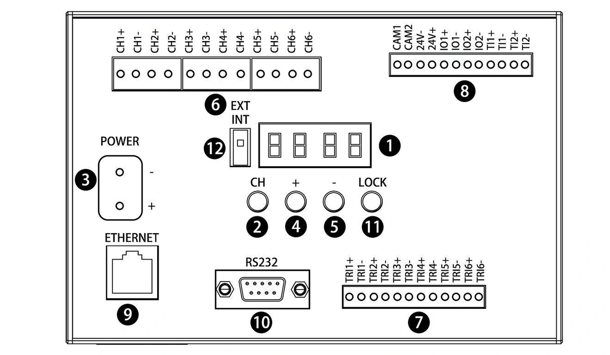
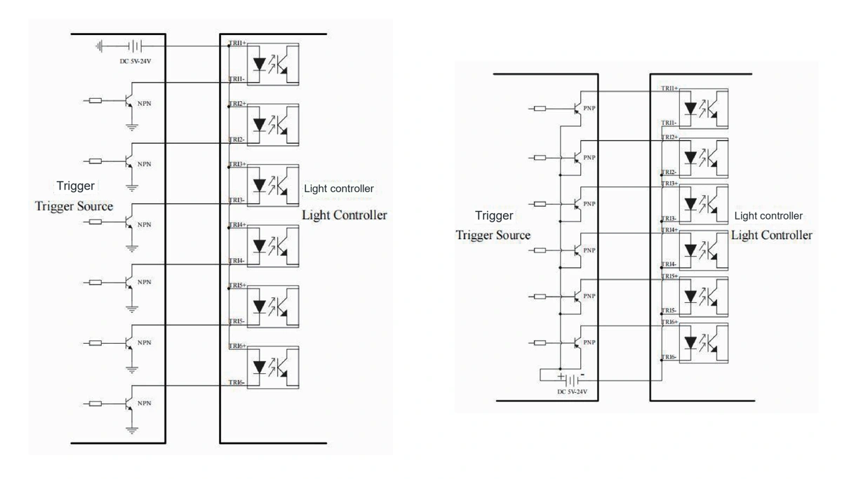
Control behaviour, connections and operating options
Review the product-specific control, interface and connection details. Every retained visual can be opened at its original resolution.
Match the inspection task to the product characteristics and verify the result on the real target.
Verify the optical result on representative samples
Define the target, imaging geometry and acceptance criteria, then validate contrast and repeatability before fixing the final configuration.
Select the controller from the load and timing requirements
Compare every applicable row before fixing the configuration.
- 1
Define the connected load
Record the light model, voltage, total power, channel count and whether intensity control is required.
- 2
Match the control method
Confirm continuous or strobe operation, trigger source, timing requirement and the available machine interface.
- 3
Compare model-level values
Use the technical table for the selected controller; do not transfer a channel or electrical value between rows.
- 4
Verify the complete system
Test the controller, light, camera trigger and production timing together before release.
Check channels, electrical interfaces and installation clearances
Match the light load, supply, trigger method and channel count to one controller configuration. Allow for connectors, wiring and service access.
Confirm the installation envelope before release
Confirm mounting, connector, cable, cooling and service clearances against the selected configuration before releasing the machine layout.