Independently controlled multi-angle illumination for PCB solder, print and glue inspection
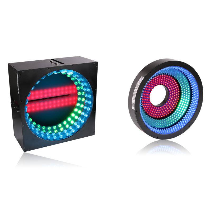
LXV-AOI distributes high-luminance LEDs across multiple illumination angles. The angle channels can be controlled independently, allowing coloured or white directional light to reveal solder shape, printed characters and glue contours on area-scan PCB stations; the related LXV-RNBRH280 rectangular RGB unit is specified for line-scan use.
- Listed configurations
- 8
- Seven AOI rings plus LXV-RNBRH280
- Supply
- 24 V
- All listed rows
- Power
- 4.4–69.2 W
- Exact configuration dependent
- Mass
- 361–6,500 g
- Exact configuration dependent
- Controller
- Strobe / analog / digital
- Match independent channel count
PCB welding quality
Use directional colour changes to make solder geometry and abnormal joints visually distinct.
Printed characters
Separate printed markings from board colour, solder and component relief.
Glue contours
Choose an angle and colour combination that reveals the edge and continuity of a glue bead.
Area- or line-scan integration
Use AOI80–275 with area-scan systems; use the rectangular LXV-RNBRH280 configuration with a line-scan system.
Measured working-distance response, field uniformity and PCB solder result
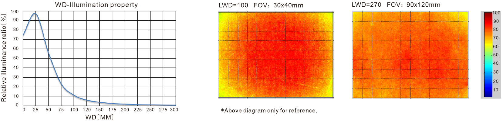
The LXV-AOI160-RGB reference covers WD 0–300 mm and two measured field conditions. A separate PCB instance shows the camera/light geometry, the original board and the colour-change result in which tin-soldering features become obvious.
LXV-AOI160-RGB optical reference
The relative-luminance curve peaks near WD 25 mm and then falls across the 0–300 mm range. The two field maps retain their stated conditions: LWD 100 mm with a 30 × 40 mm field, and LWD 270 mm with a 90 × 120 mm field.
PCB soldering-point inspection
The camera views through the central aperture while the AOI160-RGB directs separate colour angles toward the PCB. The resulting colour changes distinguish tin-soldering features from the surrounding board.
Configurable multi-angle body
Configurable items include emitting angle, outer and inner diameter, light-array quantity, colour or colour temperature, multi-area control, cable length and installation method.
- Optical model
- LXV-AOI160-RGB
- Curve range
- WD 0–300 mm; peak near WD 25 mm
- Uniformity field 1
- LWD 100 mm; FOV 30 × 40 mm
- Uniformity field 2
- LWD 270 mm; FOV 90 × 120 mm
- Application result
- Colour change makes tin soldering obvious
Match the field, aperture, colour channels and scan architecture to one exact row
The seven circular AOI rows and one rectangular RNBRH row differ in colour channels, load, mass, envelope and scan-system use. Preserve those values as a single model configuration.
- 1
Define the PCB feature
Record whether the target is solder quality, printed characters or a glue contour and how its height or colour must appear.
- 2
Select the optical condition
Choose the ring aperture, outer envelope and working-distance/field condition that clears the camera and covers the inspection area.
- 3
Choose channel colours
Validate UV/white, red/white, RGB or white output on the actual board material.
- 4
Match scan and controller
Use the intended area- or line-scan architecture and provide an independent controller channel for every active angle.
Read the product model pattern
LXV-AOI##-R/G/B/W/IR/UV- LXV
- Product prefix
- AOI
- AOI-light family
- ##
- Outer-diameter class
- R / G / B / W / IR / UV
- Colour or wavelength code; multi-channel models combine codes
Complete AOI and related line-scan reference
Power, colour, mass, drawing and scan-system assignment remain attached to each exact row.
| Model | Voltage | Power | Colour / channels | Mass | Drawing | Common | System |
|---|---|---|---|---|---|---|---|
| LXV-AOI80 | 24 V | 5.04 W | UV / White | 361 g | 1 | No | Area scan |
| LXV-AOI92 | 24 V | 4.4 W | White | 715 g | 2 | No | Area scan |
| LXV-AOI100 | 24 V | 6.2 W | Red / White | 729 g | 3 | Yes | Area scan |
| LXV-AOI122 | 24 V | 28.4 W | RGB | 867 g | 4 | Yes | Area scan |
| LXV-AOI160 | 24 V | 30.9 W | RGB | 1,215 g | 5 | Yes | Area scan |
| LXV-AOI180 | 24 V | 29.2 W | White | 1,339 g | 6 | No | Area scan |
| LXV-AOI275 | 24 V | 69.2 W | White | 2,397 g | 7 | No | Area scan |
| LXV-RNBRH280 | 24 V | 62.4 W | RGB | 6,500 g | 8 | No | Line scan |
Spectral, environment and cable reference
| Item | Reference |
|---|---|
| Red wavelength | 620–630 nm |
| Green wavelength | 525–530 nm |
| Blue wavelength | 465–470 nm |
| White colour temperature | 6600 K |
| Optional wavelengths | UV / IR configurable |
| Controller types | Strobe / analog / digital |
| Operating environment | 0–40 °C; 20–85% RH, non-condensing |
| Extension cable options | PVC flexible / bending / high-temperature; high-flex drag-chain cable |
Centre the optical axis, preserve the assigned envelope and wire each active angle independently
Eight independently bounded drawings cover the seven circular area-scan bodies and the rectangular line-scan body. Apertures, mounting circles, connector harnesses and cable counts vary substantially, so values must not be transferred between drawings.
- 01
Keep the camera optical axis centred through the selected aperture and verify lens clearance throughout focus adjustment.
- 02
Use only the mechanical drawing assigned to the exact model, including its mounting-hole depth, connector arrangement and 500 mm lead callouts.
- 03
Route every colour or angle channel to the matching strobe, analog or digital controller output.
- 04
Synchronise channel switching with the camera exposure, then confirm uniformity and solder/print/glue contrast on the real PCB.
Mechanical envelope and mounting reference
Dimensions are millimetres; diameter symbols refer to the circular body, aperture, emitting or mounting references.
| Model | Body / emitting reference | Aperture | Height | Mounting | Lead / connector |
|---|---|---|---|---|---|
| LXV-AOI80 | Ø80 | Ø24 | 22 | 4-M3 depth 4 on Ø45 | Two 500 leads shown |
| LXV-AOI92 | Ø92 | Ø35 | 24 | 4-M3 depth 5 on Ø76 | 200 + 500 harness; four connectors per cable |
| LXV-AOI100 | Ø100 body; Ø76 lower | Ø20 | 33 | 4-M3 depth 5 on Ø50 | 500 leads |
| LXV-AOI122 | Ø122 outer; Ø88 / Ø102 sections | Ø43 | 55; 37 internal | 4-M4 depth 5 on Ø68 | Multiple 500 leads |
| LXV-AOI160 | Ø160 | Ø45 | 55 | 4-M4 depth 4 on Ø68 | Multiple 500 leads |
| LXV-AOI180 | Ø180 | Ø60 | 90 | 4-M4 depth 5 on Ø104 | Multiple 500 leads |
| LXV-AOI275 | Ø275 outer; Ø255 emitting | Ø160 | 60 | 6-M4 depth 5 on Ø190 | Multiple 500 leads |
| LXV-RNBRH280 | 280 × 280 front; 130 side depth | 80 central slot; 200 inner span | 110 inner height | 8-M4 depth 4 | 500 |
Compact and mid-size AOI bodies
Each complete drawing retains its section view, aperture, mounting circle and connector arrangement without the neighbouring model.
Large AOI and rectangular line-scan bodies
The AOI160, AOI180 and AOI275 rings use different apertures and mounting circles. LXV-RNBRH280 is a separate 280 mm rectangular RGB body for line-scan use.
Verify optical result, exact model and installation together
- Target, feature and required contrast
- Field, direction and working distance
- Exact voltage, power and controller load
- Mounting, cable and thermal clearance